Chapter 2 Digital Input/Output Modules
2- 7
2
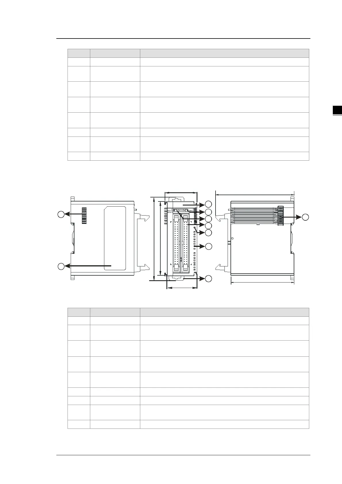
1 Model name Model name of the module
2
Y0/Y1 LED
Switches the LED indicators to their represented outputs.
3 ML connector
For the external I/O connecting cables UC-ET010-24D, UC-ET020-
4
Power LED
Indicates the power status of the module
5
Output LED
LED indicator is ON during output.
7
External module
Connects the modules
AS64AM10N-A
8
9
92
75
8
88
98.3
1
4
5
2
3
6
2
X0
64AM
40
X1
1
0
0
9
8
4
5
6
7
3
15
14
2
10
12
11
13
40
X3
2
PWR
IN
0
1
X2
0
1
1
7
38.2
35
Unit: mm
2
LED indicator
Switches the LED indicators to their represented inputs.
3
LED indicator
Switches the LED indicators to their represented inputs.
4 ML connector
For the external I/O connecting cables UC-ET010-24B, UC-ET020-
5
Power LED
Indicates the power status of the module
6 Input LED indicator If there is an input signal, the input LED indicator is ON.
7 DIN rail clip Secures the DIN rail
8
External module
Connects the modules