AS Series Module Manual
10-16
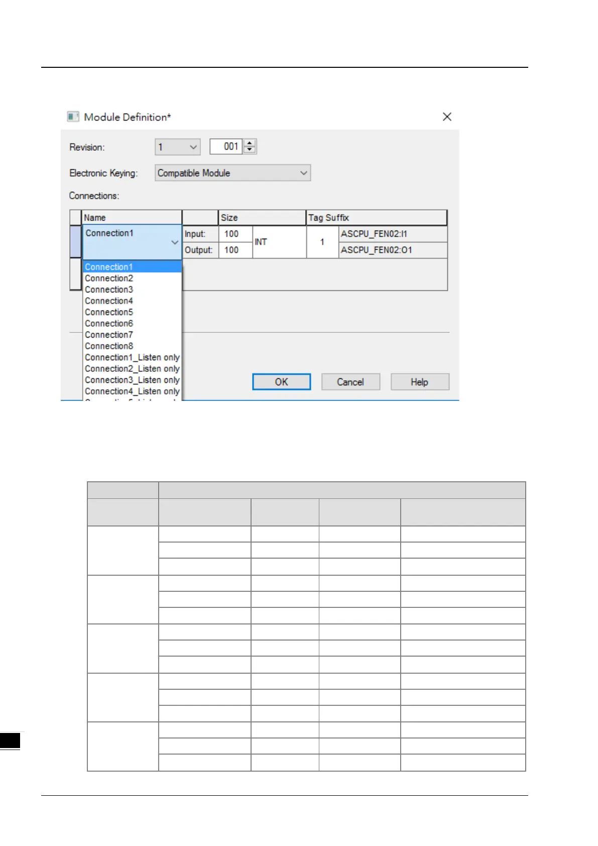
(4) Setting up the data mapping table
I: Input data (TO), Ex. Connection 1 is corresponding to PLC D3000~D3099.
O: Output data (OT), Ex. Connection 1 is corresponding to PLC D2000~D2099.
C: here corresponds to the configurations. You can edit the corresponding PLC addresses of input and output. After
editing, you need to download the parameters to Rockwell PLC.
Connection No.
Function
Instance
Length Defaults
Connection 1
Input (TO) 0x65 100 words D3000~D3099
Output (OT) 0x64 100 words D2000~D2099
Connection 2
Input (TO) 0x67 100 words D3100~D3199
Output (OT) 0x66 100 words D2100~D2199
Configuration 0x81 8 words Refer to the table below
Connection 3
Configuration 0x82 8 words Refer to the table below
Connection 4
Input (TO) 0x6B 100 words D3300~D3399
Output (OT) 0x6A 100 words D2300~D2399
Configuration 0x83 8 words Refer to the table below
Connection 5
Input (TO) 0x6D 100 words D3400~D3499
Output (OT) 0x6C 100 words D2400~D2499
Configuration 0x84 8 words Refer to the table below