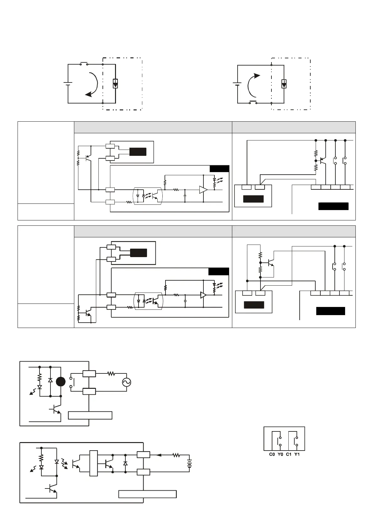
Input Point Wiring
The input signal of the input point is the DC power DC input. There are two modes of DC type wiring: SINK and
SOURCE, defined as follows:
Sink = Current flows into the input point X. Source = Current flows out of the input point X.
Sourcing
S/S
X0
Sinking
S/S
X0
DC Type
(DC Signal IN)
Loop Equivalent Circuit of Input Point Wiring Loop
+24V
24G
S/S
X0
24VDC
SOURCE
+5V
SINK
Source Type
X1 X2S/S X0+24V OV
24VDC
SINKTYPE
SINK Mode
DC Type
(DC Signal IN)
Loop Equivalent Circuit of Input Point Wiring Loop
+24V
24G
S/S
X0
24VDC
SINK
+5V
SOURC E
+24V OV
Sink Type
X1 X2S/S X0
24VDC
SOURC ETYPE
SOURCE Mode
Output Point Wiring
Y0
RY
LED
C0
RELAY OUTPUT
LOAD
POWER
DVP-**-**-11-R
1. There are two kinds of DVP-SX Series PLC
output modules: Relay and Transistor. For
relevant electrical specification, please refer to
the function specification.
2. Be careful with the connection of the common
terminals when wiring outputs. For example,
when wiring DVP12SX11R, output terminal Y0
uses one common terminal C0, Y1 uses C1, as
shown below:
Action indication: When the output point is
active, the corresponding indicator at the front
will be on.
3. Isolated circuit: The optical coupler is used to
isolate signals between PLC internal circuits
and input modules.
Y0
LED
C0
TRANSISTOR OUTPUT
LOAD
DVP-**-**-11-T
<0.3A
T
R
G