Do you have a question about the Delta DVP28SV11T2 and is the answer not in the manual?
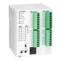
Secure PLC via M4 screw to mounting surface according to product dimensions.
Mount PLC to 35mm DIN rail using retaining clip for stability and to prevent loose wires.
Guidelines for connecting I/O wiring terminals with specified wire gauge and screw torque.
Details on DC power input, voltage range, operational limits, and shutdown behavior.
Explains SINK and SOURCE DC input modes and provides wiring diagrams for signal connections.
Covers relay and transistor output types, shared common terminals, and initial wiring.
| Model | DVP28SV11T2 |
|---|---|
| Category | I/O Systems |
| Type | PLC |
| Brand | Delta |
| Digital Inputs | 16 |
| Digital Outputs | 12 |
| Output Type | Transistor |
| Input Voltage | 24V DC |
| Power Supply | 24V DC |
| Analog Inputs | 0 |
| Analog Outputs | 0 |
| Communication Ports | RS-232, RS-485 |
| Program Memory | 16K steps |
| Pulse Outputs | 2 |
| Humidity | 5% to 95% (non-condensing) |
| Weight | 0.5 kg |
| Operating Temperature | 0°C to 55°C (32°F to 131°F) |
| Storage Temperature | -25°C to 70°C |