- 4 -
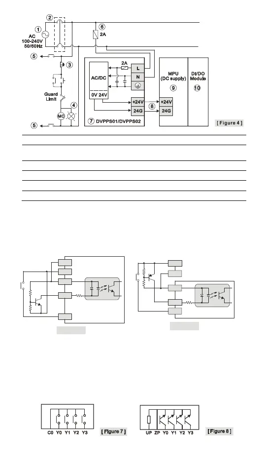
AC power supply:100 ~ 240VAC, 50/60Hz Breaker
Emergency stop: This button cuts off the system power supply when accidental
emergency takes place.
Power indicator AC power supply load
Power supply circuit protection fuse (2A) DVPPS01/DVPPS02
DC power supply output: 24 VDC, 500 mA DVP-PLC (main processing unit)
Digital I/O module
Input Point Wiring
There are 2 types of DC inputs, SINK and SOURCE. (See the example below. For
detailed point configuration, please refer to the specification of each model.)
DC Signal IN – SINK mode
Input point loop equivalent circuit
DC Signal IN – SOURCE mode
Input point loop equivalent circuit
24G
+24V
S/S
X0
X1
[ Figure 5 ]
+24V
24G
S/S
X0
X1
[ Figure 6 ]
Output Point Wiring
1. DVP-SE has two output modules on it, relay and transistor. Be aware of the
connection of shared terminals when wiring output terminals.
2. Relay output terminals, Y0 to Y3 of relay models use C0 common port. See [Figure
7]. When the output points are enabled, their corresponding indicators on the front
panel will be on.
3. Transistor output terminals, Y0 to Y3 of transistor (NPN) models use UP, ZP
common port. See [Figure 8].
 Loading...