- 5 -
4. Isolation circuit: The optical coupler is used to isolate signals between the circuit
inside PLC and input modules.
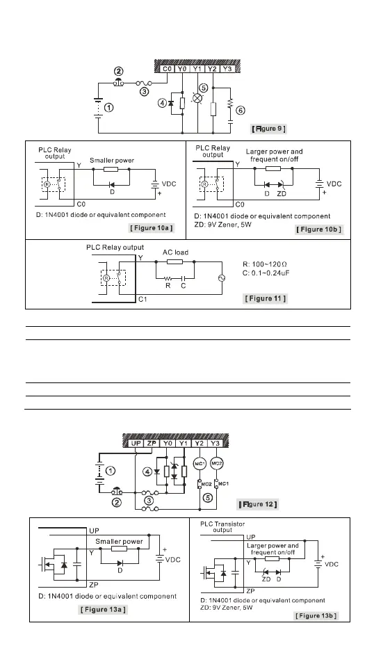
Relay (R) output circuit wiring
DC power supply
Emergency stop: Uses external switch
Fuse: 5 to10A fuse at the shared terminal of output contacts to protect the output circuit
Transient voltage suppressor (SB360 3A 60V): Extends the life span of contact.
1. Diode suppression of DC load: Used when in smaller power [Figure 10a]
2. Diode + Zener suppression of DC load: Used when in larger power and frequent On/Off
[Figure 10b]
Incandescent light (resistive load)
Absorber: Reduces the interference on AC load [Figure 11]
Transistor (T) output circuit wiring
 Loading...