Specifications TP04G-AS2
Memory Capacity 256K Byte
CPU Hitachi HD64F3064F
RAM of System 32K Byte
Communication Interface COM1: RS-232 / RS422 COM2: RS-485
Waterproof Class of Front
Panel
IP65 / NEMA4
Operating Temperature for
Hardware
0 ~ 50°C; 20 ~ 90﹪RH (non-condensing)
Storage Temperature for
Hardware
-20 ~ 60°C
Vibration
5Hz≦f<9Hz = Continuous: 1.75mm / Occasional: 3.5mm
9Hz≦f≦150Hz = Continuous: 0.5g / Occasional: 1.0g
Shock
15g peak, 11ms duration, half-sine, three shocks in each direction per axis,
on 3 mutually perpendicular axes (total of 18 shocks)
Radiated Emission CISPR11, Class A
Electrostatic Discharge
Immunity
EN61000-4-2
Radiated Immunity EN61000-4-3
Electrical Fast Transient EN61000-4-4
Weight / Dimensions 0.24kg; 147×97×35.5mm (Width(W) × Height(H) × Deep(D))
Cooling Method Natural Air Cooling
[ Program Copy Card
TP04 series provides Program Copy Card Function to copy user program, system function and passwords that is
different from the copy program. It is used to copy the whole HMI environment settings and application programs
to another HMI rapidly. Using Program Copy Card saves time and manpower. The operation is as follows.
Definition: Program Copy Card → PCC, TP Series → TP
(TP→PCC) (PCC→TP)
Step 1 Turn the switch on the PCC to TP→PCC Turn the switch on the PCC to PCC→TP
Step 2 Insert the PCC into the extension slot of TP Insert the PCC into the extension slot of TP
Step 3 Input the power to TP Input the power to TP
Step 4
It will display “remove PCC” on the screen and
power on again.
It will display “remove PCC” on the screen and
power on again.
HMI Display Message
(TP→PCC) (PCC→TP)
Step 1
If the TP model type does not correspond with the
model type of program of PCC, TP will display “TP
series and PCC is different. Press Enter to
Confirm TP seriesÆPCC. Press Esc to Exit”.
If there is no program in PCC, TP will display “The
PCC is Empty. PCC→TP series is illegal”.
Step 2
TP will display “TP→PCC series Please wait!”
during transmission.
TP will display “PCC→TP series Please wait!”
during transmission.
Step 3
TP will display “Please Remove the PCC and
Reboot” when transmission is completed.
TP will display “Please Remove the PCC and
Reboot” when transmission is completed.
\ Password Function
If the user forgot the password, the password can be cleared by using the following code: 8888. This universal
code will clear the password and all TP04 series internal programs. The TP04 series will be reset to the factory
settings by using this code also. Please pay close attention when using it.
The password can be the alphabet from A to Z or the number from 0 to 9. But it must use the function
keys F0 ~ F9 to input the password characters. Please refer to the following table.
Function Key Use Method Function Key Use Method
F0 / F5
Scrolls in a loop as follows
0→5→A→B→C→D→E→F→0
F3 / F8
Scrolls in a loop as follows
3→8→Q→R→S→T→U→V→3
F1 / F6
Scrolls in a loop as follows
1→6→G→H→I→J→K→1
F4 / F9
Scrolls in a loop as follows
4→9→W→X→Y→Z→4
F2 / F7
Scrolls in a loop as follows
2→7→L→M→N→O→P→2
] Hardware Operation
When the user wants to startup TP04 series, a 24VDC power is needed. After applying 24VDC power to TP04
series, it will enter into the startup display and then enter the user-designed program. Pressing Esc key and
holding on for 5 seconds can return to system menu. There are five selections in the system menu and are
described below.
SELECTIONS EXPLANAION
Download Program
Use the connection cable (DVPACAB530) to connect the TP04 serial
communication port RS-232 to a PC. Then use the TPEdit software to download an
application program to TP04.
Upload Program
Use the connection cable (DVPACAB530) to connect the TP04 serial
communication port RS-232 to a PC. Then use the TPEdit software to upload an
SELECTIONS EXPLANAION
application program from TP04.
Copy Program
Transfer a program between two TP04 units.
1: transmit programs
2: receive programs
When transmit programs and data between two TP04 units. Set one TP04 to
“Receive Program” mode and the other TP04 to “Transmit Program” mode. Please
use twisted pair wires to connect the two units via the RS-485 ports.
TP04 Settings
There are 9 items that used to modify TP04 system settings:
1. Communication protocol: Setting the address of TP04, the control port of PLC,
and the communication string for either RS-232 or RS-485.
2. Contrast: Adjust the contrast of LCM display screen.
3. Back-light: adjust the automatic turn off time of LCM. Setting range is 00 ~ 99
minutes. If set to 00, the LCM Back-light will not turn off.
4. Date and Time: It is used to set the TP04 built-in RTC including year, month,
day, hour, minute, second and week. Also the internal battery capacity display
is shown here.
5. Buzzer: Used to set the buzzer sound, normal mode or quiet mode.
6. Language Setting: Used to set the displayed language. English, Traditional
Chinese, Simplified Chinese or user defined language.
7. Password setting: Used to set, enable, and disable the password function. If the
password function is enabled, it will require the user to input a password before
entering any system menu. The factory password is 1234.
8. Startup display: Used to select the TP04 startup display. User can select “user
defined” to use the file that designed by TPEdit and download to TP04.
9. Comm. indicator: The user can determine if the RS-232 and RS-485 LEDs will
blink or not during communication.
PLC Connection
There are three methods to connect to PLC:
1. Using TP04 serial communication port (COM1) RS-232: set 8-pin DIP switch to
RS-485 mode and connect the cable (DVPACAB215 or DVPACAB230) to
program communication I/O RS-232C of PLC.
2. Using extension communication port (COM2): set 8-pin DIP switch to RS-485
mode and connect 5-pin removal terminal of extension communication port to
RS-485 of PLC with twisted pair.
3. Using extension communication port (COM2): set 8-pin DIP switch to RS-422
mode and connect four pins (6, 7, 8, 9) of 9 PIN D-SUB male to RS-422 of PLC
with 4-wire cable.
Execution
Execute the internal program that download from TPEdit or transmitted from other
TP04 units. When program is in execution, the user can return to system menu by
pressing Escape / Exit (Esc) key for 5 seconds.
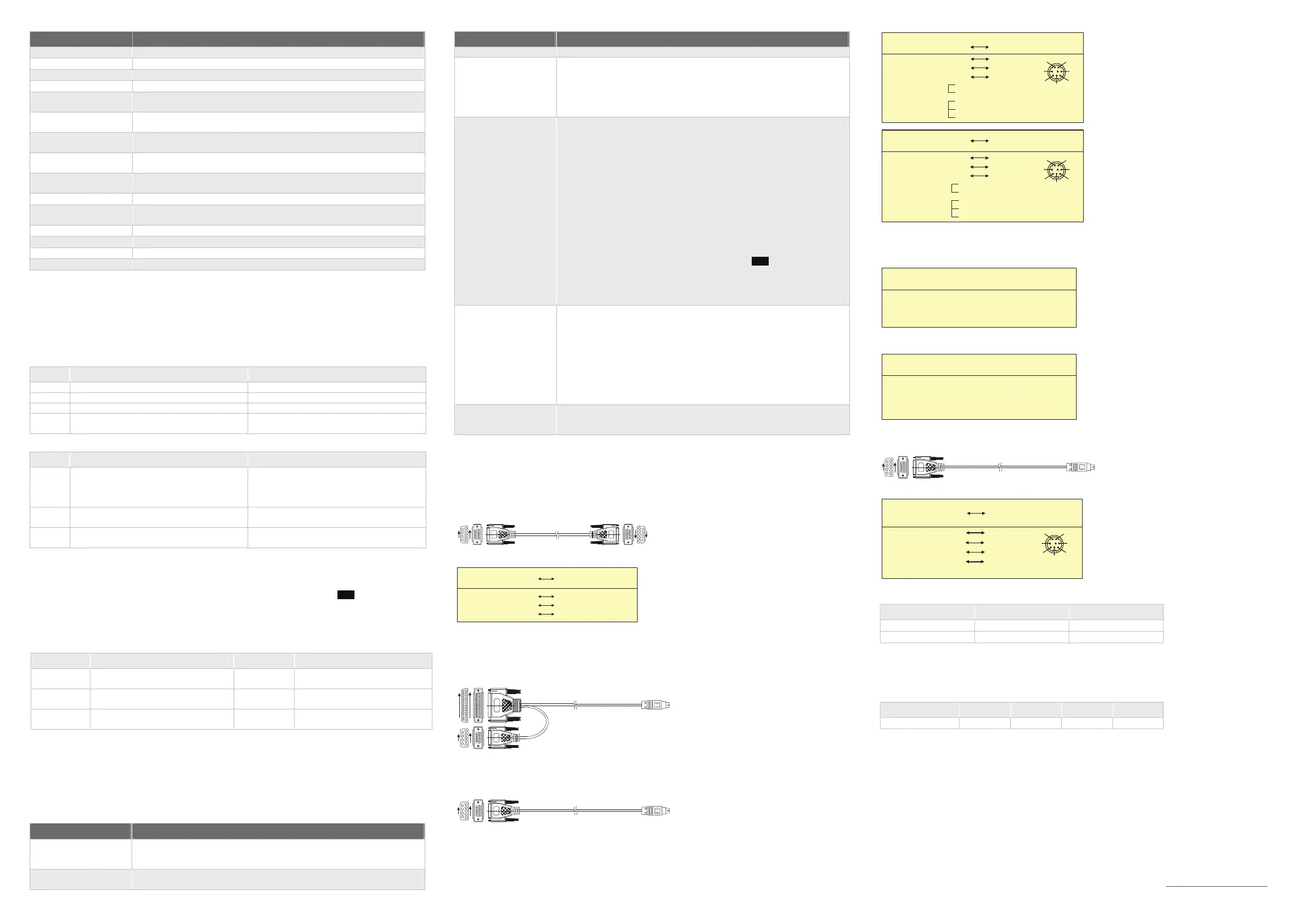
^ Communication Connection
TP04G may connect to a PC by using connection able DVPACAB515
PC or TP02 / 04G
1
5
6
9
9 PIN D-SUB
TO PC (RS-232)
TO TP02 / 04G
5
1
9
6
9 PIN D-SUB
9 PIN D-SUB female
Rx 2
GND 5
5 GND
PC COM Port
9 PIN D-SUB female
3 Tx
2 Rx
TP 02 / 04G COM Port
Tx 3
TP04G may connect to a DVP-PLC by using connection cable DVPACAB215 / DVPACAB230 /
DVPACAB2A30
1. DVPACAB215 / DVPACAB230
TO PC or TP02 / 04G
1
13
14
1
5
6
9
25 PIN D-SUB
9 PIN D-SUB
TO PLC
MINI DIN TERMINAL
2. DVPACAB2A30
TO PC or TP02 / 04G
1
5
6
9
9 PIN D-SUB
TO PLC
MINI DIN TERMINAL
8 PIN MINI DIN25 PIN D-SUB female
PC / TP COM Port PLC COM1 Port
Tx
2
GND 7
8 PIN MINI DI N9 PIN D-SUB female
PC / TP COM Port
PLC COM1 Port
Rx 2
GND 5
6
8
20
4
5
1
4
6
7
8
4 Rx
8 GND
1,2 5V
1
2
3
4
5
6
7
8
5 Tx
Rx 3
Tx 3
1
2
3
4
5
6
7
8
4 Rx
8 GND
1,2 5V
5 Tx
The Pin definition of 9 PIN D-SUB
1. RS-232
3 Tx
5 GND
RS-232 9 PIN D-SUB male
TP02 / 04G COM Port
2 Rx
2. RS-422
8 Tx +
RS-422 9 PIN D-SUB male
9 Tx -
TP02 / 04G COM Port
7 Rx -
6 Rx +
3. DVPACAB630 (RS-422)
TO TP02 / 04G
1
5
6
9
9 PIN D-SUB
TO PLC
MINI DIN TERMINAL
8 PIN MINI DIN
9 PIN D-SUB female
TP02 / 04G COM Port
MITSUBISHI FX-PLC
1
2
3
4
5
6
7
8
Tx+ 8
2 Rx +
3 SG
GND 5
COM1 Port RS-422
7 Tx+
Rx+
6
Rx -
7 4 Tx -
Tx - 9
1 Rx -
Switch between RS-422 / RS-485 (by using 8-PIN DIP switch)
8-PIN DIP Switch RS-485 RS-422
SW1 ~ SW4 On Off
SW5 ~ SW8 Off On
_ Battery Life and Precision of Calendar Timer
Battery Life
Temperature (°C) -20 0 20 60
Life (Year) 1.972 2.466 2.712 2.835
Precision of Calendar Timer
1. At 0°C / 32°F, less than -117 seconds error per month.
2. At 25°C / 77°F, less than 52 seconds error per month.
3. At 55°C / 131°F, less than -132 seconds error per month.
The content of this instruction sheet may be revised without prior notice. Please consult our distributors or
download the most updated version at http://www.delta.com.tw/industrialautomation
 Loading...