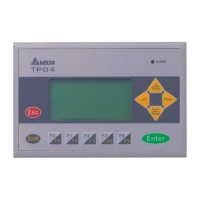
3.2 Function Specification
ITEM TP04G-AS2
Screen STN-LCD
Color Monochromatic
Backlight
The back-light automatic turn off time is 1~99 minutes
(0 = do not turn off)
(back-light life is about 50 thousand hours at 25℃)
Resolution 128X64 Points
Display Range 72mm (W) X 40mm (H); 3.00” (diagonal preferred)
Contrast Adjustment 10-step contrast adjustment
Font
ASCII: characters (including European Fonts)
Taiwan: (BIG 5 code) traditional Chinese character font
China: (GB2324-80 code) simplified Chinese character font
5X 8: 25 words X 8 rows
8X8: 16 words X 8 rows
8X12: 16 words X 5 rows
Maximum words x rows, for
each font size
8X16: 16 words X 4 rows
Font Size ASCII: 5X8, 8X8, 8X12, 8X16
Alarm Indication LED (RED)
1. Power on indication (blink for three times)
2. Will blink for communication error or other alarm
3. Special Indication by user programming
RS-232 Indication LED
(Yellow)
It will blink when transmitting program and communicating by using
RS-232.
Display Screen
RS-485/RS-422 Indication
LED (green)
It will blink when communicating by using RS-485/RS-422.
Program Memory 256KB flash memory
Serial Communication Port
RS-232 (COM1)
Unsynchronized transmission method: RS-232
Data length: 7 or 8 bits, Stop bits: 1or 2 bits
Parity: None/Odd/Even,
Transmission speed: 9600bps~115200bps
RS-232: 9 PIN D-SUB male
Extension Communication
Port RS-422/RS-485 (COM2)
Unsynchronized transmission method: RS-485/RS-422
Data length: 7 or 8 bits, Stop bits: 1 or 2 bits
Parity: None/Odd/Even
Transmission speed: 9600bps~115200bps
RS-422: 9 PIN D-SUB male
RS-485: 5-Pin removal terminal
Extension Slot 1. Update program version 2.The slot for program copy card
Battery Cover DC 3V battery for HMI
External Interface
5-Pin Removal Terminal There are DC 24V input and RS-485 input
4 PROGRAM COPY CARD
TP04G provides function of program copy card to copy user program, system function and passwords that is
different from the copy program. It is used to copy the whole HMI environment settings and application programs
to another HMI rapidly. It saves time and manpower. The operation is as follows.
Definition: Program Copy Card ÆPCC, TP Series ÆTP
Step TPÆPCC PCCÆTP
1 Turn the switch on the PCC to TPÆPCC Turn the switch on the PCC to PCCÆTP
2 Insert the PCC into the extension slot of TP Insert the PCC into the extension slot of TP
3 Input the power to TP Input the power to TP
4 It will display “remove PCC” on the screen and power
on again
It will display “remove PCC” on the screen and
power on again
HMI display message
Copy HMI program to PCC (TPÆPCC) Copy PCC program to HMI (PCCÆTP)
If the TP model type does not correspond with the
model type of program of PCC, TP will display “TP
series and PCC is different. Press Enter to Confirm
TP seriesÆPCC. Press Esc to Exit”.
If there is no program in PCC, TP will display “The PCC
is Empty. PCCÆTP series is illegal”.
TP will display “TP ÆPCC series Please wait!” during
transmission.
TP will display “TP ÆPCC series Please wait!” during
transmission.
TP will display “Please Remove the PCC and Reboot”
when transmit complete.
TP will display “Please Remove the PCC and Reboot”
when transmit complete.
5 PASSWORD FUNCTION
1. If you forgot the password, it can be cleared by using the following code: 8888. This universal code will clear the
password and all TP04 internal programs. The TP04 will be reset to the factory settings.
2. Users may use 0~9 and A~Z as characters for the password. But it must use the function keys F0~F4 to input the
password characters.
F0/F5: scrolls in a loop as follows 0 Æ 5 Æ A Æ B Æ C Æ D Æ E Æ F Æ 0
F1/F6: scrolls in a loop as follows 1 Æ 6 Æ G Æ H Æ I Æ J Æ K Æ 1
F2/F7: scrolls in a loop as follows 2 Æ 7 Æ L Æ M Æ N Æ O Æ P Æ 2
F3/F8: scrolls in a loop as follows 3 Æ 8 Æ Q Æ R Æ S Æ T Æ U Æ V Æ 3
F4/F9: scrolls in a loop as follows 4 Æ 9 Æ W Æ X Æ Y Æ Z Æ 4
6 HARDWARE OPERATION
After power supplies to TP04G, the alarm indication LED will blink for three times and startup display, on the LCM
display area will show “No User Data in Memory, Press ESC 5 seconds, Return to System”.
The steps to Startup the TP04G:
1. Connect power line,
2. Apply 24V DC power,
3. Enter into the startup display,
4. Enter the user-designed program,
5. Press Esc key and hold on for 5 seconds to return to system menu.
There are five selections in the system menu and are described below.
SELECTIONS EXPLANATION
Download
Program
Use the connection cable (DVPACAB530) to connect the TP04 serial communication port
RS-232 to a PC. Then use the TPEdit software to download an application program to
TP04.
Upload Program
Use the connection cable (DVPACAB530) to connect the TP04 serial communication port
RS-232 to a PC. Then use the TPEdit software to upload an application program from
TP04.
Copy Program
Transfer a program between two TP04 units.
1: transmit programs
2: receive programs
When transmit programs and data between two TP04 units. Set one TP04 to “Receive
Program” mode and the other TP04 to “Transmit Program” mode. Please use twisted pair
wires to connect the two units via the RS-485 ports.
TP04 Settings
There are 9 items that used to modify TP04 system settings:
1. Communication protocol: Setting the address of TP04, the control port of PLC, and the
communication string for either RS-232 or RS-485.
2. Contrast: Adjust the contrast of LCM display screen.
3. Back-light: adjust the automatic turn off time of LCM. Setting range is 00~99 seconds. If
set to 00, the LCM Back-light will not turn off.
4. Date and Time: It is used to set the TP04 built-in RTC including year, month, day, hour,
minute, second and week. Also the internal battery capacity display is shown here.
5. Buzzer: Used to set the buzzer sound, normal mode or quiet mode.
6. Language Setting: Used to set the displayed language. English, Traditional Chinese,
simplified Chinese or user defined language.
7. Password setting: Used to set, enable, and disable the password function. If the
password function is enabled, it will require the user to input a password before entering
any system menu. The factory password is 1234.
8. Startup display: Used to select the TP04 startup display. User can select “user defined”
to use the file that designed by TPEdit and download to TP04.
9. Comm. indicator: The user can determine if the RS-232 and RS-485 LEDs will blink or
not during communication.
PLC Connection
There are three methods to connect to PLC:
1. Using TP04 serial communication port (COM1) RS-232: set 8-pin DIP switch to RS-485
mode and connect the cable (DVPACAB215 or DVPACAB230) to program
communication I/O RS-232C of PLC.
2. Using extension communication port (COM2): set 8-pin DIP switch to RS-485 mode
and connect 5-pin removal terminal of extension communication port to RS-485 of PLC
with twisted pair.
3. Using extension communication port (COM2): set 8-pin DIP switch to RS-422 mode
and connect four pins (6, 7, 8, 9) of 9 PIN D-SUB male to RS-422 of PLC with 4-wire
cable.
Execution
Execute the internal program that download from TPEdit or transmitted from other TP04
units. When program is in execution, you can return to system menu by pressing
Escape/Exit (Esc) key for 5 seconds.
7 COMMUNICATION CONNECTION
TP04G may connect to a PC by using connection cable DVPACAB530
1
5
6
9
9 PIN D-SUB
ON PC (RS-232)
ON TP02/04G
5
1
9
6
9 PIN D-SUB
9 PIN D-SUB female
Rx 2
GND 5
5 GND
PC COM Port
9 PIN D-SUB female
3 Tx
2 Rx
TP02/04G COM Port
Tx 3
TP04G may connect to a DVP-PLC by using connection cable DVPACAB215/ DVPACAB230 /
DVPACAB2A30
DVPACAB215/ DVPACAB230
PC or TP02/04G
1
13
14
1
5
6
9
25 PIN D-SUB
9 PIN D-SUB
8 PIN MINI DIN
ON PLC
DVPACAB2A30
8 PIN MINI DIN25 PIN D-SUB female
PC/HMI COM Port PLC COM1 Port
Tx 2
GND 7
8 PIN MINI DIN9 PIN D-SUB female
PC/HMI COM Port PLC COM1 Port
4 Rx
8 GND
Rx 2
GND 5
1,2 5V
1
2
3
4
5
6
7
8
12
3
4
5
6
7
8
4 Rx
8 GND
1,2 5V
6
8
20
4
5
1
4
6
7
8
5 TxRx 3
Tx 3
5 Tx
The Pin definition of 9 PIN D-SUB
1. RS-232 2. RS-422
3 Tx
5 GND
RS-232 9 PIN D-SUB male
TP04G-AS2 COM Port
2 Rx
8 Tx +
RS-422 9 PIN D-SUB male
9 Tx -
TP04G-AS2 COM Port
7 Rx -
6 Rx +
DVPACAB630 (RS-422)
8 PIN MINI DIN
9 PIN D-SUB female
HMI COM Port MITSUBISHI FX-PLC
Rx - 7
Tx+ 8
1
2
3
4
5
6
7
8
7 Tx+
2 Rx+
Tx - 9
3 SG
GND 5
Rx+
COM1 Port RS-422
6
4 Tx -
1 Rx -
Switch between RS-422 / RS-485 (by using 8-PIN DIP switch)
8-PIN DIP switch RS-485 RS-422
SW1~SW4 On Off
SW5~SW8 Off On
8 BATTERY LIFE AND PRECISION OF CALENDAR TIMER
Battery life
Temperature (°C)
-20 0 20 60
Life (year) 1.972 2.466 2.712 2.835
Precision of calendar timer
At 0°C/32°F, less than –117 seconds error per month.
At 25°C/77°F, less than 52 seconds error per month.
At 55°C/131°F, less than –132 seconds error per month.

 Loading...