Chapter 5 Parameters_VFD-B Series
Revision 10/2005, BE13, SW V4.08 5-67
ON
05-00
05-01
05-02
05-03
05-04
05-05
05-06
05-07
05-08
05-09
05-10
05-11
05-12
05-13
05-14
OFF
OFF
1 2 3 4
5
6 7 8 9 10 11 12 13 14
15
ON
OFF
OFF
05-17
05-18
05-19
05-20
05-21
05-22
05-23
05-24
05-25
05-26
05-27
05-28
05-29
05-30
05-31
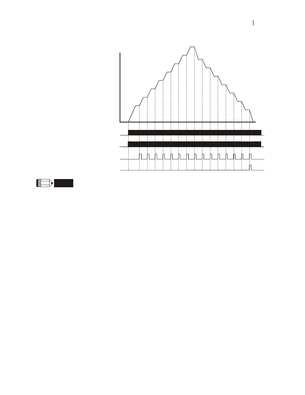
Frequency
Time
Program operation
command
Program operation
indication
Step operation indication
Program operation fulfillment indication
multi-function input terminals
multi-function output terminals
multi-function output terminals
multi-function input terminals
NOTE
The above diagram shows one complete PLC cycle. To restart the cycle, turn the PLC program
off and on again.
Example 2 (Pr.05-15 = 2): Continuously execute program cycles:
The diagram above shows the PLC program stepping through each speed. Setting Pr.05-15 to 2 continuously
executes the program. To stop the PLC program, one must either pause the program or turn it off. (Refer to Pr.04-
04 to 04-09 values 14 and 15).
Example 3 (Pr.05-15 = 3) Execute one cycle step by step:
The example below shows how the PLC can perform one cycle at a time, within a complete cycle. Each step will
use the accel/decel times in Pr.01-09 to Pr.01-12. Note that the actual time each step stays at its intended
frequency is reduced, due to the time for accel/decel.