The MS300 automatically switches to PLC mode when the external multi-function input terminals
(MI1–MI7) are in PLC Mode selection bit 0 (51) or PLC Mode selection bit1 (52), and the terminal
contact is closed or open. In this case, keypad switching is invalid. The corresponding actions are
listed in Table 16-2.
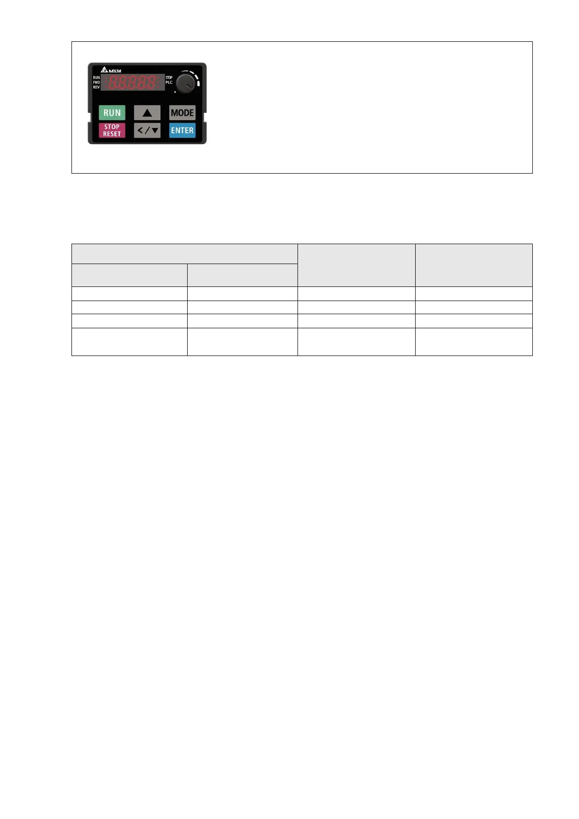
Using the MS300 digital keypad to implement the PLC functions
When the PLC screen from the keypad is set to PLC0 (or “Disable” on KPC-CC01), the
built-in PLC is disabled and you cannot use WPLSoft or ISPSoft to connect to it.
When the PLC screen from the keypad is set to PLC1 (or “PLC Run“ on KPC-CC01), the
built-in PLC is enabled and you can use WPLSoft or ISPSoft to connect to it through
Modbus.
When the PLC screen from the keypad is set to PLC2 (or “PLC Stop” on KPC-CC01), the
built-in PLC is enabled and you can use WPLSoft or ISPSoft to connect to it. However, the
programs in the built-in PLC do not work.
When the built-in PLC is enabled (PLC1 or PLC2), you can switch between PLC Run or
PLC Stop through WPLSoft or ISPSoft.
The external terminal control method is the same as shown in Table 16-2 above.
NOTE:
When the input / output terminals (MI1–MI7, Relay, and MO) are included in the PLC program, these
input / output terminals are used only by the PLC. For example, when the PLC program controls Y0
during PLC operation (PLC1 or PLC2), the corresponding output terminal relay (RA / RB / RC)
operates according to the program. At this time, the multifunctional input / output terminal setting has
no effect. Because these terminal functions are already being used by the PLC, you can determine
the DI / DO / AO in use by the PLC by looking at Pr.02-52, 02-53, and 03-30.
When the PLC program uses special register D1040, the corresponding AO contact AFM is occupied.
Pr.03-30 monitors the action state of the PLC function analog output terminals; bit 0 corresponds to
the AFM action state.