EasyManuals Logo

Delta VFD2A7MS43ANSAA User Manual

Delta VFD2A7MS43ANSAA
805 pages
To Next Page IconTo Next Page
To Previous Page IconTo Previous Page
Page #712 background imageLoading...
Page #712 background image
Chapter 16 PLC Function ApplicationsMS300
703
Command
Function
PLS
Upper differential output
Operand
X0–X17
Y0–Y17
M0–M799
T0159
C0–C79
D0–D399
Upper differential output command: when X0 switches from OFF to ON (rising edge-
triggered), the PLS command is executed, and M0 sends one pulse with the pulse
length consisting of one scanning period.
Ladder diagram:
X0
M0
PLS
M0
Y0
SET
Timing diagram:
X0
M0
Y0
Time for one scan cycle
Command code:
Description:
LD
X0
Load Contact A of X0
PLS
M0
M0 Upper differential
output
LD
M0
Load Contact A of M0
SET
Y0
Y0 Action continues
(ON)
Command
Function
PLF
Lower differential output
Operand
X0–X17
Y0–Y17
M0–M799
T0159
C0–C79
D0–D399
Lower differential output command: when X0 switches from ON to OFF (falling edge-
triggered), the PLF command is executed, and M0 sends one pulse with the pulse
length consisting of one scanning period.
Ladder diagram:
X0
M0
PLF
M0
Y0
SET
Timing diagram:
X0
M0
Y0
Time for one scan cycle
Command code:
Description:
LD
X0
Load Contact A of X0
PLF
M0
M0 Lower differential
output
LD
M0
Load Contact A of M0
SET
Y0
Y0 Action continues
(ON)
Command
Function
END
End of Program
Operand
N/A
An END command must be added to the end of a ladder diagram program or
command program. The PLC scans the program from address 0 to the END
command, and then returns to address 0 and begins scanning again.

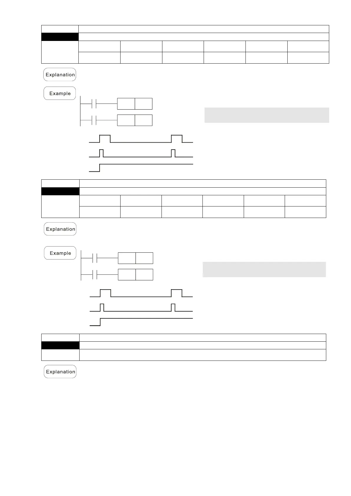
Table of Contents

Questions and Answers:

Question and Answer IconNeed help?

Do you have a question about the Delta VFD2A7MS43ANSAA and is the answer not in the manual?

Delta VFD2A7MS43ANSAA Specifications

General IconGeneral
BrandDelta
ModelVFD2A7MS43ANSAA
CategoryDC Drives
LanguageEnglish

Related product manuals