'T{PUT
'
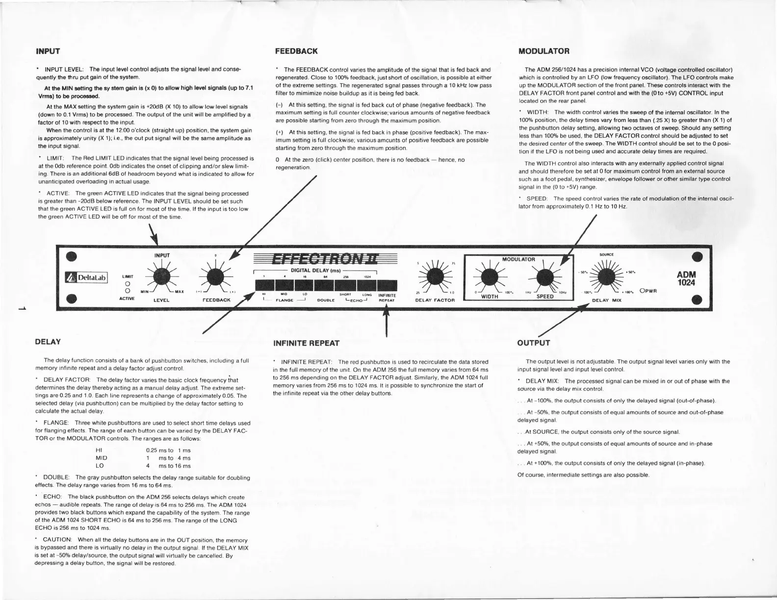
INPUT LEVEL:
Tha input loEl control adiusts tha signal
let€l
ard conse'
quently
ihs
thru
put
gain
ol
th€ systom.
Al
tho MIN $nirlg
ltp.y slorn
grln
B
(x
0)
to sllow
high lml lign ls
(up
to 7.1
Vrmr) to b6
pro6ad.
Al lhe MAX
stting tho systsm
gain
is
+20d8
(X
10) to
allow
low lewl
signsls
(down
to
0.1
Vrms)
lo bo
prm8sad.
Ths
output ot
the
unit
will
bo amplilisd by a
lactor
o,
l0 with resp€ct lo ths
inpul.
Wh6n ths control
is at tho
12:00
o'clock
(straighl
up)
position,
the
system
gsin
is approximately uniry
(X
l); i.e.,
tho oul
pul
signal will b€ the smo amplitude
as
the input signal.
'
LIMIT:
The Bed LIMIT
LED
indicates that
the
signal
level
being
pr@essed
is
at the odb Gleence
poinl.
odb indicaies the onset
ot clipping ard/or slew
limit-
ing. Thore
is
an
additionsl
6tB ot headroom
b€yond
what
is
indicated
to allow for
unanticipatad overloading
in
aclual usge.
'
ACTIVE:
The
gEn
ACTIVE LEO indicales
thal the signal being
prGessd
is
greater
lhan
-20d8
below
retersnce.
The INPUT LEVEL
should be set such
that
the
grmn
ACTIVE
LED is tull on for most
of the lime.
lf
the input
is too low
lhe
green
ACTIVE
LED will be otf tor
most ot the time.
DELAY
The
delay
lunclion
consists
of a bank of
pushbutton
switches. including
a
lull
memory inlinite
repeat and
a delay lactor
adjusl control.
'
DELAY
FACTOR:
The
delay factor varies the
basic ctock
frequency ihat
determines the delay thereby
acting as
a
manual
delay adjust.
The
extreme set-
tings are 0.25 and 1.0.
Each line represnts
a change ol approximately 0.05. The
*lected
delay
(via pushbulton)
can be multiplied
by
ihe delay lactor
stting to
calculate the actual
delay.
'
FLANGE: Three white
pushbuttons
are usd
to
select
short time delays used
tor flanging
ertects.
The
range ol each button can
be
varied
by
the
DELAY
FAC-
TOR
or
the MOOULATOFI
controls.
The
ranges
are as
lollows:
Hl 0.25 ms to
1
ms
MID 1
msto 4ms
LO 4
mstol6ms
'
DOUBLE: The
gray pushbution
selecls the
delay
range
suitable
lor
doubling
etfects.
The
delay range varies lrom 16
ms to 64 ms.
'
ECHO: The
black
pushbutton
on the ADM 256 selects
delays
which
create
echos
-
audible
repeats.
The range
ol delay
is
64 ms lo 256 ms. The ADM 1024
provides
two
black bullons which
expand the Gpability
ol
the
system.
The range
o,
the ADM 1024
SHORT ECHO is
64 ms to 256 ms. The range
of the LONG
ECHO is
256 ms to
1024
ms.
'
CAUTION: When
all the
delay buttons are in the
OUT
position,
the memory
is bypased
and there is virtually no
delay
in
the
ouiput signal It the OELAY MtX
is
sl
at
-50% delay/source.
the output
signal
will virtually
be emelled. By
depre$in9 a delay button, ihe
signal will b€ restored.
FEEDBACK
' Ihe FEEOBACK conirol varies the
amplitude of the signal
that is ted back ard
regeneraled.
Close to
'l0O%
f*dback,
just
shorl of o$illation,
is
possiblo
at eilhet
o, the extreme settings. The
regeneratod signal
pass
lhrough a
10
kllz
low
pass
lilter to
mimimize
noise
buildup
as
it is being fed back.
(-)
At this
stting.
the
signal is
ted
back oui o,
phas
(negative
f*dback). The
maximum stting is full
counter cl@kwi*; various amounts of
negalive ,eedback
are
possible
starting
rrom
zero through ihe maximum
posilion.
(+)
Al
this setting, the signal is fed back in
phas (positive
fedback). The
max-
imum setting is tull
clockwise;
various
amounls of
posilive
feedback are
possible
starting
from zero through the maximum
position.
0 At the aro
(click)
center
position,
there is no fedback
-
hence, no
regeneration.
MODULATOR
The
ADM 256/1024 has
a
precision
inlernal VCO
(voltage
controlled
oscillelor)
which is cmtrolled
by
an
LFO
(low
lrequency
o$illator). The LFO
cmlrols
make
up
the MODULATOR *clion ol the
,ront
panel.
Thes
controls
intemct with the
DELAY FACTOH
f ront
parel
control
and with tho
(0
to
+5V)
CONTROL input
locat€d on the
rear
panel.
'
WIDTH:
The width control wries the srvesp
of th€ intemal osillator.
ln the
10O9o
posilion,
the delay limes vary from less
ihan
(.25
X)
to
groater
than
(X
l) of
the
pushbution
delay stting, allowing
two Glaves ot swoep. Should any satting
less than
1009!
be used, the
DELAY
FACTOR control should be adiusted to set
the desired
center ol the swep.
The WIDTH
control should be st to the 0
pGi-
tion il the LFO is not being usd and acurate delay tires are required.
The wIDTH
conlrol
also
interacls
wilh any sxternally applied control signal
and should
therefore be st at 0 for maximum control lrom an external source
such as a
foot
pedal,
synlhesizer, envelope followor
or
other similar
type control
signal in the
(0
lo
+5V)
range.
'
SPEEDT The speed control varies
lhe rale of
modulation o, the inlemal oscil-
lator from approximatelv 0.1 Hz
to
10
Hz.
OUTPUT
The output level is not adjustable. The
output signal
level varies
only
with
lhe
input signal level
and
input level
conlrol.
'
DELAY MIX: The
processed
signal
can be mixed
in
or out of
pha*
with
the
source via the delay mix
control.
. . . At
-1009o,
lhe output coosists
o,
only the delayed signal
(out-ol-phas€).
. . At -50o/o.
the outpul consists
o,
equal amounts of source and out-of-phas
delayed signal.
.
.
.At
SOUBCE, the output consists
only
of the
source
signal.
. . . At
150%,
the
output consisls ot equal amounls ol surce and in-pha*
delayed signal.
. . . At
+1000/0,
ihe
oulput consists of only the delayed signal
(in-phas).
Ol cour*,
intermediale
settings are also
po$ible.
INFINITE
REPEAT
'
INFINITE REPEAT: The red
pushbutton
is used to recirculate the data stored
in the ,ull memory
ol
the
unit. On
lhe ADM
256
the ,ull memory varies from 64 ms
to
256 ms
depending
on
the OELAY
FACTOR adjust.
Similarly.
the ADM 1024 full
msmory
varies
from
256 ms
to
1
024 ms. lt is
possible
to synchronize the start o,
the
inlinite repeat via
the other delay buttons.
fur.*
#
O
acnw
LEvEt-
FEEDBA.( ,#:
:**"".*
o
ADM
1t24
o
#"*x
 Loading...