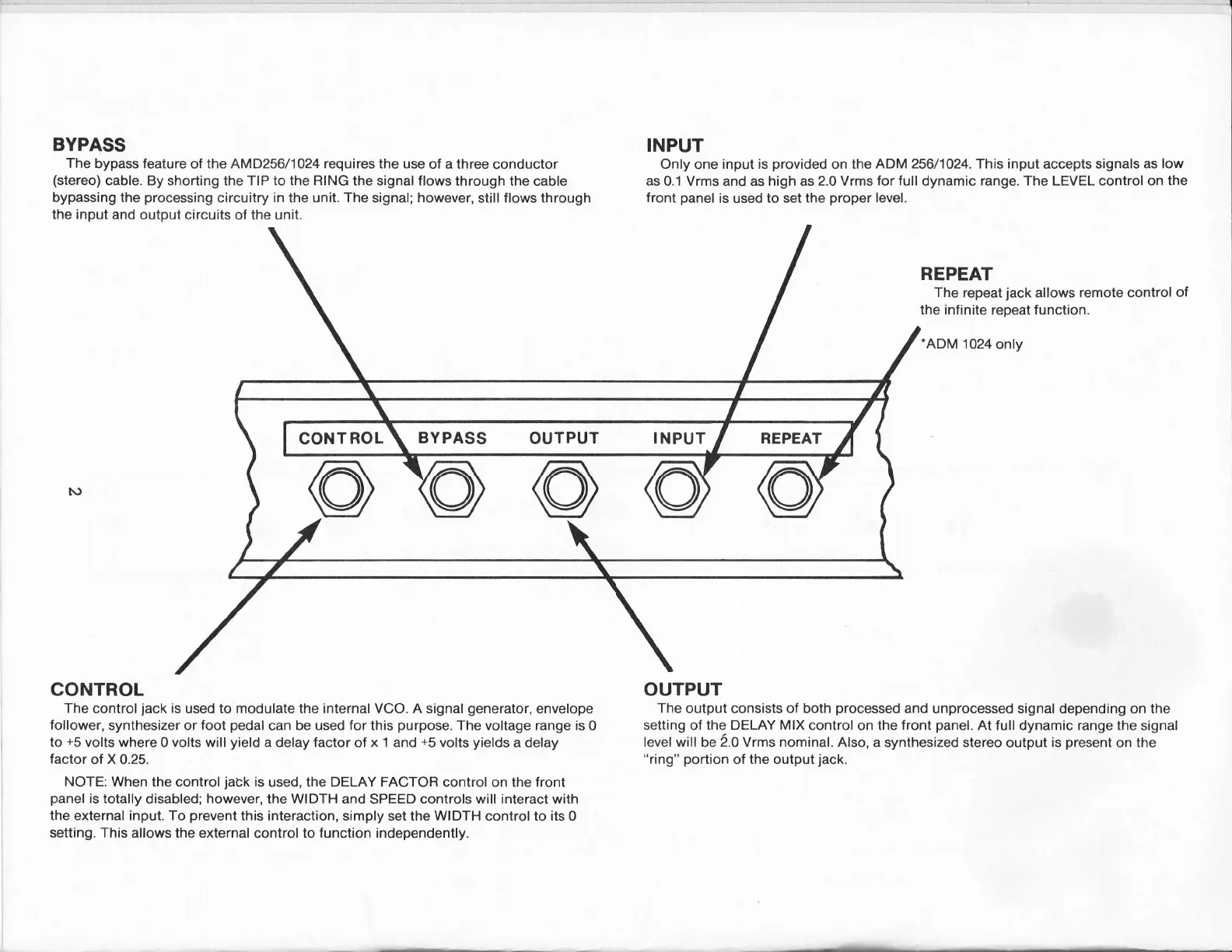
BYPASS
The
bypass feature
of
the AMD256/1A24 requires the use
ol a three
conductor
(stereo)
cable.
By shorting the
TIP
to the
RING
the signal flows through the
cable
bypassing the
processing
circuitry
in
the
unit. The
signal;
however,
still flows through
the input and
output circuits
of
the unit.
INPUT
Only
one
input is
provided
on the
ADM 256/1024.
This
input
accepts
signals as low
as
0.1 Vrms and as high as
2.0 Vrms for full dynamic range. The LEVEL control on
the
front
panel
is
used
to set the
proper
level.
REPEAT
The
repeat
jack
allows
remote
control
of
the infinite
repeat
function.
.ADM
1024
only
OUTPUT
The
output consists ol both
processed
and unprocessed signal
depending on
the
setting of the DELAY
MIX
control
on
the front
panel.
At full
dynamic
range the
signal
level will
be
2.0 Vrms nominal.
Also, a synthesized stereo
output
is
present
on the
"ring"
portion
of
the output
jack.
CONTROL
The
control
jack
is
used to modulate the internal VCO. A signal
generator,
envelope
follower,
synthesizer or foot
pedal
can be
used for
this
purpose.
The
voltage
range is
0
to
+5
volts
where 0 volts will
yield
a delay factor
of
x
'l
and
+5
volts
yields
a delay
factor
of
X
0.25.
NOTE: When
the control
jack
is
used, the DELAY FACTOR control
on
the front
panel
is
totally disabled;
however,
the WIDTH and
SPEED
controls will interact with
the external input. To
prevent
this interaction, simply set the WIDTH control
to
its 0
setting. This allows the external
control
to function independently.
BYPASS
OUTPUT
INPUT
 Loading...