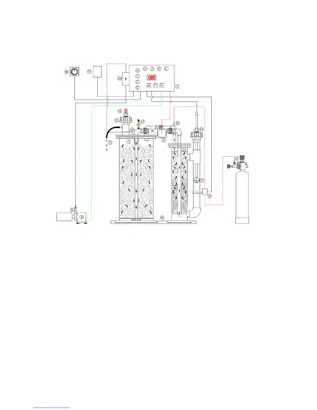
Connections and general layout
Use the following diagram as an overview to allow you to connect the reactor together. Details of assembly
are given in the text.
Key Control Functions
1. Media chamber
A – Mode button
2. Gassing chamber B – Water flow rate per 24 hours in litres*
3. Control unit C – Degassing after ‘X’ litres*
4. Feed pump D – Recirculation pump speed %*
5. Non-return valve E – Process active/complete %
6. Solenoid valve F – Increase button for items marked *
7. Float switch G – Decrease button for items marked*
8. CO2 bottle and Regulator H – Activity indicator green/yellow/red
9. Recirculation pump J – CO2 valve open/active
10. PH probe position K – CO2 Bottle empty (audible alarm)
11. Outlet from reactor L – Degassing cycle running
12. Top-up fill cap for media
13. Bleed valve
14. Float cap
15. CO2 feed to gassing chamber
16. Base plate
17. Power supply to controller
18. Optional timer system
 Loading...