Do you have a question about the DEMAG DIC 002 Series and is the answer not in the manual?
Introduction to the Demag quality frequency inverter and its compliance with standards.
Explains safety symbols (DANGER, WARNING, CAUTION) and their meanings for hazard communication.
Details the purpose and target audience of the operating instructions for safe use.
Outlines manufacturer's liability limitations and warranty conditions for proper use.
Defines roles like Manufacturer, Owner, and Operating Personnel, specifying required qualifications.
Provides contact information and procedures for technical support, spare parts, and service inquiries.
Overview of safety aspects for personnel protection and equipment operation, emphasizing hazards.
Specifies the correct application of frequency inverters and limitations to prevent hazards and damage.
Details potential dangers like electric shock, warnings about non-compliance, and specific hazards.
Outlines owner's obligations regarding safety measures, compliance with regulations, and personnel training.
Specifies the qualifications and age requirements for personnel working on the installation.
Recommends necessary protective gear for personnel working on or with the installation based on hazard assessment.
Provides technical parameters for the STO safety function, including PL, SIL, MTTFd, DC, and CCF ratings.
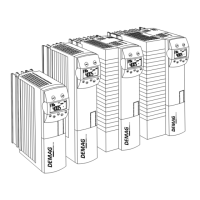
Explains the structure and meaning of the Dedrive Compact STO inverter model code for identification.
Presents dimensions and thermal resistance values specific to the DIC-4-xxx-C model.
Offers detailed technical specifications for DIC-2 and DIC-4 frequency inverters based on current codes.
Illustrates derating diagrams for output current and coolant temperature based on altitude and ambient conditions.
Describes the modular nature of inverters and how the scope can be customized with optional components.
Lists the items included in the scope of delivery for specific inverter models and their part numbers.
Details the scope of delivery for DIC-2-018 and DIC-4-014 to 040 frequency inverter models.
Lists the components included in the scope of delivery for DIC-4-045 to 120 frequency inverter models.
Specifies the items included in the scope of delivery for DIC-4-150 to 210 frequency inverter models.
Provides safety warnings and guidelines for handling, packing, and storing the frequency inverter to prevent damage.
Details critical safety precautions for working with live components and during installation to prevent injury.
Instructions for installing optional communication and extension modules into the inverter's slots.
Guidelines for selecting a suitable installation site, ensuring proper ventilation, cleanliness, and accessibility.
Covers general mechanical installation aspects, including IP20 enclosure requirements and vibration resistance.
Safety instructions and conditions for connecting cables, including earthing, separation of cables, and EMC measures.
Illustrates and describes the correct procedures for connecting the frequency inverter to the 3ph/400 V AC mains supply.
Provides detailed guidance on connecting motors and braking resistors, including cable length recommendations and diagrams.
Explains the function and connection of control terminals, including digital inputs, outputs, and power supply.
Crucial safety measures and precautions to prevent hazards during the initial startup and commissioning process.
Outlines the general procedure for commissioning, including drive control via terminals and initial parameter settings.
Describes key assignments, displays, and menu navigation for parameter configuration using the KP500 keypad.
Explains how to use the Parcom Compact software for configuring and programming inverter parameters via PC.
Step-by-step guide for practical commissioning, including parameter setup, motor identification, and checking drive behavior.
Introduces the parameter structure and methods for configuration via PC software or keypad unit.
Details how to acknowledge error messages and restore default settings using the Program parameter.
Explains the function and calculation of brake application time relative to deceleration and control signals.
Covers the assignment and functions of digital inputs and outputs for controlling drive behavior and status.
Describes how step-based setpoint value generation is activated and configured using digital inputs.
Explains setpoint value memory functions activated by input signals for controlling drive speed.
Information on connecting and configuring rotary encoders for speed measurement and control, including operation modes.
Explains how to set a maximum output frequency limit to prevent over-frequency operation and trigger error messages.
Interprets the status indicated by LEDs and display elements (RUN, WARN, FAULT) for operational status and errors.
Lists and explains various warning messages that can occur, their codes, and potential causes.
Details error codes, their meanings, and troubleshooting steps for diagnosing and resolving faults.
Provides safety instructions and guidelines for maintenance, dust removal, and storage of the frequency inverter.
Lists key parameters, their ranges, default settings, and explanations for configuration and operation.
Lists part numbers for various filters and reactors required for different inverter models and frequency ranges.
Catalog of optional modules like keypad units, communication modules, and interface converters with part numbers.
Presents the overall circuit diagram of the frequency inverter, showing connections for power, motor, encoder, and control signals.