Do you have a question about the DEMAG TEREX CC8800 and is the answer not in the manual?
Assembly of the crawler-mounted crane, Step 1, focusing on Part 3.
Assembly of the crawler-mounted crane, Step 2, using parts 4 and 8 (pins).
Assembly of the crawler-mounted crane, Step 3, focusing on Part 9.
Assembly of the crawler-mounted crane, Step 4, using parts 2 and 8 (pins).
Assembly of the crawler-mounted crane, Step 5, using Part 23, lowering chassis onto crawler.
Assembly of the crawler-mounted crane, Step 6, using parts 6, 7, and 8.
Assembly of the crawler-mounted crane, Step 7, attaching superstructure to undercarriage.
Assembly of the crawler-mounted crane, Steps 8 & 9, using parts 10 and 5.
Assembly of the crawler-mounted crane, Steps 10 & 11, hydraulic connections for drive container.
Assembly of the crawler-mounted crane, Steps 12-14, using parts 14, 23, and 16.
Assembly of the crawler-mounted crane, Steps 15 & 16, erecting the frame.
Assembly of the crawler-mounted crane, Step 17, attaching back stroke cylinders for mast.
Assembly of the crawler-mounted crane, Step 18, assembling boom sections (parts 13, 18, 15).
Assembly of the crawler-mounted crane, Step 19, using bracing rods and connections.
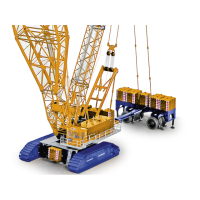
Assembly of the crawler-mounted crane, Step 19 continuation, using dolly and counterweight parts.
Assembly of the crawler-mounted crane, Step 20, parts for 60m SSL configuration.
Assembly of the crawler-mounted crane, Step 21, reeving ropes for the EZW (E-drum).
Assembly of the crawler-mounted crane, Step 22, reeving ropes for the W2 (Crosshead W2).
Assembly of the crawler-mounted crane, Step 22 continuation, reeving ropes for various sheave heads.
Visual guide to reeving ropes for the crane, showing hook block and boom configurations.
| Max Lifting Capacity | 1, 600 t |
|---|---|
| Max Load Moment | 24, 000 tm |
| Number of Axles | 9 |
| Total Transport Width | 3 m |
| Transport Width | 3 m |
| Operating Weight | 1200 t |
| Counterweight | 400 t |