Instruction Rev02
0mm
10 20
30
40
50
60
70
80
90
Thank you for choosing DENALI
We know you would rather be riding your bike than wrenching on it, so we go the extra
mile to make sure our instructions are clear and as easy to understand as possible. If
you have any questions, comments, or suggestions don’t hesitate to give our experts
a call at 401.360.2550 or visit WWW.DENALIELECTRONICS.COM
Please Read Before Installing
DENALI products should always be installed by a qualified motorcycle technician. If
you are unsure of your ability to properly install a product, please have the product
installed by your local motorcycle dealer. DENALI takes no responsibility for damages
caused by improper installation. Caution: When installing electronics it is extremely
important to pay close attention to how wires are routed, especially when mounting
products to the front fender, front fork, or fairing of your motorcycle. Always be sure
to turn the handlebars fully left, fully right, and fully compress the suspension to
ensure the wires will not bind and have enough slack for your motorcycle to operate
properly.
Installation Tips
We strongly recommend using medium strength liquid thread locker on all screws and
bolts. It is also important to ensure that all hardware is tightened to the proper torque
specifications as listed in your owner’s manual. For included accessory hardware
please refer to the default torque specifications provided below. Inspect all hardware
after the first 30 miles to ensure that proper torque specifications are maintained.
Hardware Sizing Guide
Not sure what size bolt you have? Use this ruler to measure screws, bolts, spacers, etc.
Remember, the length of a screw or bolt is measured from the start of the “mounting
surface” to the end of the screw, so only include the screw head when measuring
countersunk screws.
M5 44.5 in-lbs 3.5 ft-lbs 5.0 Nm
M6 78.0 in-lbs 6.5 ft-lbs 9.0 Nm
M10 - 30.0 ft-lbs 41.0 Nm
M12 - 52.0 ft-lbs 71.0 Nm
ft-lbs NmBolt Size
0in 1 2
3
What’s In The Box?
DENALIELECTRONICS.COM
Instruction Manual
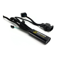
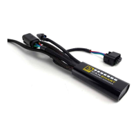
(a) CANsmart™ Controller..........................................................Qty 1
(b) 3-Pin 5ft Horn Extension.......................................................Qty 1
(c) 3-Pin 5ft LED Light Extension.................................................Qty 2
(d) 3-Pin Brake Light Wiring Adapter............................................Qty 1
(e) Zip Tie...............................................................................Qty 4
(f) Adhesive Dual Lock..............................................................Qty 1
(g) USB to Micro USB Programming Cable.....................................Qty 1
Kit Contents
(b)
(c)
(f)
(d)
(e)
(g)
(a)
GEN II CANsmart™ Controller
DNL.WHS.11702
BMW K1600 Series
BMW S1000XR
BMW F850GS & GSA
BMW F750GS
ONLINE
USER GUIDE
DENALIelectronics.com/BMW-CANsmart-User-Guide