EasyManua.ls Logo

Denali T3 - User Manual

Denali T3
2 pages
Print Icon
To Next Page IconTo Next Page
Loading...
Instruction Rev00
0mm
10 20
30
40
50
60
70
80
90
Thank you for choosing DENALI
We know you would rather be riding your bike than wrenching on it, so we go the extra
mile to make sure our instructions are clear and as easy to understand as possible. If
you have any questions, comments, or suggestions don’t hesitate to give our gear
experts a call at 401.360.2550 or visit WWW.DENALIELECTRONICS.COM
Please Read Before Installing
DENALI products should always be installed by a qualified motorcycle technician. If
you are unsure of your ability to properly install a product, please have the product
installed by your local motorcycle dealer. DENALI takes no responsibility for damages
caused by improper installation. Caution: When installing electronics it is extremely
important to pay close attention to how wires are routed, especially when mounting
products to the front fender, front forks, or fairing of your motorcycle. Always be sure
to turn the handlebars fully left, fully right, and fully compress the suspension to
ensure the wires will not bind and have enough slack for your motorcycle to operate
properly.
Installation Tips
We strongly recommend using medium strength liquid thread locker on all screws,
nuts, and bolts. It is also important to ensure that all hardware is tightened to the
proper torque specifications as listed in your owner’s manual. For included accessory
hardware please refer to the default torque specifications provided below. Inspect all
hardware after the first 30 miles to ensure proper torque specifications are
maintained.
Hardware Sizing Guide
Not sure what size bolt you have? Use this ruler to measure screws, bolts, spacers, etc.
Remember, the length of a screw or bolt is measured from the start of the “mounting
surface” to the end of the screw, so only include the screw head when measuring
countersunk screws.
M3 10.0 in-lbs - 1.0 Nm
M4
23.0 in-lbs
- 2.5 Nm
M5 44.5 in-lbs 3.5 ft-lbs 5.0 Nm
M6 78.0 in-lbs 6.5 ft-lbs 9.0 Nm
M8 - 13.5 ft-lbs 18.0 Nm
M10 - 30.0 ft-lbs 41.0 Nm
M12 - 52.0 ft-lbs 71.0 Nm
in-lbs
ft-lbs NmBolt Size
0in 1 2
3
What’s In The Box?
DENALIELECTRONICS.COM
T3 Crashbar Mount Kit
LAH.T3.10100
Instruction Manual
(a) Mounting Bracket ................................................................Qty 2
(b) VHB Double-Sided Tape........................................................Qty 1
Kit Contents Tools Required
#2 Phillips Head Screw Driver, Step Drill Bit, Heat Gun, Rubbing Alcohol
(b)
(a)
Question and Answer IconNeed help?

Do you have a question about the Denali T3 and is the answer not in the manual?

Summary

Pre-Installation Safety and Guidance

Installation Tips

Recommends thread locker and proper torque specs for hardware. Inspect after 30 miles.

Hardware Sizing Guide

Ruler to measure screws, bolts, and spacers for proper identification.

Kit Contents and Tools

Kit Contents

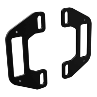
Lists the included components like mounting brackets and VHB tape.

Tools Required

Lists necessary tools for installation, such as screwdrivers and heat guns.

Assembling the Crashbar Mounts

Assembling the Mount

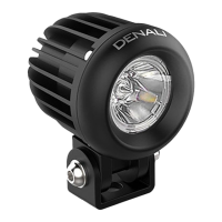
Steps for attaching the T3 Light Pod to the Mounting Bracket using screws.

Applying the Double-Sided Tape

Instructions for cutting and applying VHB tape to the mount.

Installing the Crashbar Mounts

Internal Wiring

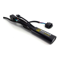
Detailed steps for routing the harness internally through the crashbar.

External Wiring

Steps for routing the harness externally along the crashbar.

Overview

The DENALI T3 Crashbar Mount Kit (LAH.T3.10100) is an accessory designed to integrate DENALI T3 Light Pods onto a motorcycle's crashbar. This kit facilitates the secure mounting of auxiliary lighting, enhancing visibility and safety for riders.

Function Description:

The primary function of the T3 Crashbar Mount Kit is to provide a robust and discreet mounting solution for DENALI T3 Light Pods. It allows for the integration of these lights directly onto the motorcycle's crashbar, offering two distinct wiring options: internal and external. Internal wiring routes the light harness through the crashbar tubing, providing a clean, concealed look and protection for the wiring. External wiring routes the harness along the outside of the crashbar, secured by zip ties, which may be simpler for some installations. The kit is designed to work with T3 Light Pods, which are sold separately, utilizing self-tapping screws included with the T3 Pods for attachment to the mounting brackets. The VHB Double-Sided Tape ensures a strong, vibration-resistant bond between the mounting bracket and the crashbar surface.

Important Technical Specifications:

  • Model Number: LAH.T3.10100
  • Compatibility: Designed for DENALI T3 Light Pods (sold separately).
  • Mounting Method: Utilizes a mounting bracket and VHB Double-Sided Tape for attachment to the crashbar.
  • Wiring Options: Supports both internal and external wiring configurations.
  • Internal Wiring Hole Size: Requires a 14mm hole to be drilled into the crashbar for internal routing.
  • Hardware Torque Specifications:
    • M3: 10.0 in-lbs (1.0 Nm)
    • M4: 23.0 in-lbs (2.5 Nm)
    • M5: 44.5 in-lbs (3.5 ft-lbs / 5.0 Nm)
    • M6: 78.0 in-lbs (6.5 ft-lbs / 9.0 Nm)
    • M8: 13.5 ft-lbs (18.0 Nm)
    • M10: 30.0 ft-lbs (41.0 Nm)
    • M12: 52.0 ft-lbs (71.0 Nm)
  • Kit Contents:
    • (a) Mounting Bracket: Qty 2
    • (b) VHB Double-Sided Tape: Qty 1 (to be cut into four pieces)
  • Tools Required:
    • #2 Phillips Head Screw Driver
    • Step Drill Bit (recommended for 14mm hole)
    • Heat Gun
    • Rubbing Alcohol

Usage Features:

The installation process is broken down into two main stages: assembling the crashbar mounts and installing them onto the crashbar.

Assembly of Crashbar Mounts (Section 1):

  1. Assembling the Mount (1.1):
    • The light harness from the T3 Pod is fed through the center of the mounting bracket.
    • The T3 Light Pod is then attached to the mounting bracket using the self-tapping screws provided with the T3 Pod. This process is repeated for the second mounting bracket and T3 Pod.
  2. Applying the Double-Sided Tape (1.2):
    • The strip of VHB Double-Sided Tape is cut into four even pieces.
    • For external wiring, the harness is placed in the wire channel of the crashbar mount before applying the VHB tape.
    • The tape pocket surface on the crashbar mount is prepped and cleaned with rubbing alcohol, then gently warmed with a heat gun.
    • Two pieces of the VHB tape are applied to the back of each crashbar mount after peeling off one side of the liner.

Installing the Crashbar Mounts (Section 2):

This section details the two wiring options:

  1. Internal Wiring (2.1):

    • Step One: A 14mm hole must be drilled into the crashbar surface where the T3 Light Pod will be mounted. A step drill bit is recommended for precision. If the crashbar tubing is closed at the end, a second 14mm hole will be needed for the harness to exit.
    • Step Two: The harness is fed through the drilled hole(s) and fished through the crashbar tubing until it exits.
    • Step Three: The crashbar surface is prepped and cleaned with rubbing alcohol and gently warmed with a heat gun. The remaining liner from the VHB Double-Sided Tape is removed, and the assembled mount (with the T3 Pod) is applied to the crashbar with moderate pressure. This method provides a clean, integrated look by concealing the wiring within the crashbar.
  2. External Wiring (2.2):

    • Step One: The crashbar surface is prepped and cleaned with rubbing alcohol and gently warmed with a heat gun. The remaining liner from the VHB Double-Sided Tape is removed, and the assembled mount (with the T3 Pod) is applied to the crashbar with moderate pressure.
    • Step Two: The harness is run along the outside of the crashbar and secured using zip ties (not included). This method is generally simpler and does not require drilling into the crashbar.

Maintenance Features:

  • Thread Locker: It is strongly recommended to use medium strength liquid thread locker on all screws, nuts, and bolts to prevent loosening due to vibration.
  • Torque Specifications: All hardware must be tightened to the proper torque specifications as listed in the owner's manual or the provided table for accessory hardware. This ensures secure fastening and prevents damage.
  • Post-Installation Inspection: After the initial installation, all hardware should be inspected after the first 30 miles of riding to ensure proper torque specifications are maintained. This is crucial for long-term reliability and safety.
  • Wiring Inspection: When installing electronics, particular attention should be paid to wire routing. The handlebars should be turned fully left and right, and the suspension fully compressed, to ensure that wires do not bind and have sufficient slack for proper motorcycle operation. This prevents wire damage and potential electrical issues.
  • Surface Preparation: For optimal adhesion of the VHB Double-Sided Tape, the mounting surface on the crashbar must be thoroughly prepped and cleaned with rubbing alcohol and gently warmed with a heat gun. This ensures a strong, lasting bond.

General Safety and Installation Guidelines:

  • DENALI products should always be installed by a qualified motorcycle technician. If the user is unsure of their ability to properly install the product, it is advised to have it installed by a local motorcycle dealer. DENALI takes no responsibility for damages caused by improper installation.
  • The hardware sizing guide (0mm to 90mm ruler) is provided to help identify bolt and screw sizes, ensuring the correct hardware is used for each step. The length of a screw or bolt is measured from the start of the "mounting surface" to the end of the screw, excluding the screw head unless it's a countersunk screw.

Denali T3 Specifications

General IconGeneral
BrandDenali
ModelT3
CategoryMotorcycle Accessories
LanguageEnglish

Related product manuals