EasyManua.ls Logo

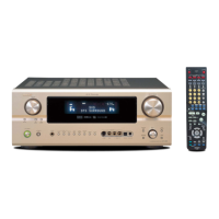
Denon AVC-2890 User Manual

Denon AVC-2890
94 pages
To Next Page IconTo Next Page
Page #1 background imageLoading...
Page #1 background image
AVC-2890
SERVICE MANUAL
MODEL
AVR-2805/985
AV SURROUND RECEIVER/AMPLIFIER
For U.S.A. & Canada model
16-11, YUSHIMA 3-CHOME, BUNKYO-KU, TOKYO 113-0034 JAPAN
X0199 V.01 DE/CDM 0404
Some illustrations using in this service manual are
slightly different from the actual set.
Please use this service manual with referring to the
operating instructions without fail.
For purposes of improvement, specifications and
design are subject to change without notice.
本文中に使用しているイラストは、説明の都合上現物
と多少異なる場合があります。
修理の際は、必ず取扱説明書を参照の上、作業を行っ
てください。
サービスをおこなう前に、このサービスマニュアルを
必ずお読みください。本機は、火災、感電、けがなど
に対する安全性を確保するために、さまざまな配慮を
おこなっており、また法的には「電気用品安全法」に
もとづき、所定の許可を得て製造されております。
従ってサービスをおこなう際は、これらの安全性が維
持されるよう、このサービスマニュアルに記載されて
いる注意事項を必ずお守りください。
本機の仕様は性能改良のため、予告なく変更すること
があります。
補修用性能部品の保有期間は、製造打切後8年です。
注 意
Ver. 1
w
w
w
.
x
i
a
o
y
u
1
6
3
.
c
o
m
Q
Q
3
7
6
3
1
5
1
5
0
9
9
2
8
9
4
2
9
8
T
E
L
1
3
9
4
2
2
9
6
5
1
3
9
9
2
8
9
4
2
9
8
0
5
1
5
1
3
6
7
3
Q
Q
TEL 13942296513 QQ 376315150 892498299
http://www.xiaoyu163.com

Table of Contents

Question and Answer IconNeed help?

Do you have a question about the Denon AVC-2890 and is the answer not in the manual?

Denon AVC-2890 Specifications

General IconGeneral
TypeAV Receiver
Channels7.1
Frequency Response10 Hz - 100 kHz
Input Sensitivity/Impedance200 mV/47 kOhms
Signal-to-Noise Ratio100 dB
Tuner TypeFM/AM
Audio Formats SupportedDolby Digital, DTS
Total Harmonic Distortion0.08%
Video Inputs/OutputsComposite
Audio Inputs/OutputsAnalog
Digital Inputs2 Coaxial, 2 Optical
Dimensions (W x H x D)434 x 171 x 384 mm

Summary

SAFETY PRECAUTIONS

LEAKAGE CURRENT CHECK

Procedure to check leakage current or line-to-chassis resistance for safety.

About Safety Important Parts

Identifies parts with special safety characteristics and their importance.

CAUTION IN SERVICING

Initializing AV SURROUND RECEIVER

Steps for initializing the receiver after component replacement.

ADJUSTMENT PROCEDURES

Audio Section Idling Current

Detailed steps for adjusting the idling current in the audio section.

VIDEO SECTION ADJUSTMENT

Component Video Level Adjustment

Procedure for setting component video output levels using a test disc.

BLOCK DIAGRAMS

Audio Section Block Diagram

Overview of the audio signal flow and component connections.

LEVEL DIAGRAMS

Front Channel Level Diagrams

Signal level specifications for front channels.

Center/Surround Channel Level Diagrams

Signal level specifications for center and surround channels.

Test Mode Operations

µcom/DSP Error Display Mode

Procedure to check for microcomputer and DSP errors via the display.

COMPONENT IDENTIFICATION

Semiconductor ICs

List and details of integrated circuits used in the unit.

CONNECTORS AND INDICATORS

Optical Connectors

Description of optical input/output connectors.

Front Panel Indicators

Explanation of front panel indicators.

PRINTED WIRING BOARDS

1U-3469 Power PWB Unit

Layout and component placement for the power PWB.

PARTS LISTING NOTES

Resistor Notation Explanation

Guide to understanding resistor part numbers and values.

Capacitor Notation Explanation

Guide to understanding capacitor part numbers and values.

Printed Wiring Board Parts

1U-3469 Power PWB Parts

Detailed parts list for the 1U-3469 power PWB.

EXPLODED VIEWS AND PARTS

Parts List

List of parts corresponding to the exploded view diagram.

PACKING AND ACCESSORIES

Exploded View Packing List

List of packing materials and accessories with regional destinations.

SCHEMATIC DIAGRAMS

AUDIO IN UNIT Schematic

Circuit diagram for the audio input unit.

DIGITAL UNIT Schematic

Circuit diagram for the digital unit, part 1 of 3.

POWER UNIT Schematic

Circuit diagram for the power supply unit.

Related product manuals