Do you have a question about the Denon DCD-2560 and is the answer not in the manual?
Essential warnings and precautions for preventing fire, shock hazard, and ensuring safe operation of the CD player.
Recommendations for optimal performance and stable operation using the semiconductor laser, including temperature guidelines.
Information on potential radio/television interference and compliance with FCC Rules for Class B computing devices.
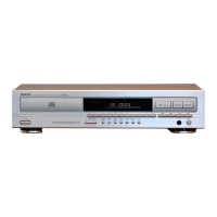
Overview of key technological features including SL.C. circuit, robust power supply, and user-friendly design with hidden controls.
Instructions for releasing the shipping lock mechanism before operating the CD player to prevent damage.
Guidelines for handling, cleaning, and storing compact discs to maintain sound quality and player longevity.
Detailed description of front panel buttons, display window sections, and their respective functions for operation.
Diagrams and instructions for connecting the CD player's audio and digital output jacks to external audio equipment.
Step-by-step guide on how to open, close, and load discs into the CD player's disc holder correctly.
Instructions on initiating CD playback and the process for stopping the unit during or after playback.
Methods for playing specific tracks, moving between tracks, and searching within tracks using various playback functions.
Guidance on how to program a sequence of tracks for custom playback order on the CD player.
How to temporarily pause playback and use manual search functions for fast forward or reverse listening.
Techniques for finding specific tracks or inserting silent gaps between tracks using search and auto space features.
Instructions for playing tracks in random order and using the auto edit function for tape recording preparation.
Detailed steps for using the time edit function to synchronize CD playback with cassette tape lengths for recording.
Using the pick function to manage blank spaces and the link function for editing multiple discs sequentially.
How to fade out audio during playback or fade in from a paused state using the FADER button.
Setting fade-out times in advance and using the peak search function for recording level adjustments.
Adjusting the playback speed using the pitch control buttons and its effect on digital output and time display.
Instructions for inserting batteries into the RC-232 remote control and basic usage guidelines.
Important precautions for using the remote control, including sensor alignment, signal range, and avoiding simultaneous operation.
Overview of remote control buttons for disc holder, playback, search, and volume adjustments.
How to set the remote control to program mode for track sequencing or use direct search for track selection.
Technical details on audio performance, dynamic range, signal-to-noise ratio, and supported disc formats.
Information on power supply, consumption, dimensions, weight, functions, and supplied accessories with product details.
Diagrams identifying key components of the laser pick-up mechanism, including the OP unit and nameplate.
Wiring connection diagrams for the KSS-151A accessory flexible wire terminals and its connection to the main P.W.B.
Precautions for storage, handling, eye protection, and avoiding damage from electrostatic discharge or surge currents.
Information on X-axis actuator, metal bearing care, and methods for diagnosing laser pick-up deterioration.
Step-by-step instructions for removing the top cover of the unit, including screw locations and cover removal direction.
Guidance on detaching the front panel and bottom cover, including screw removal and hook management.
Procedures for manually moving the loader frame and detaching the whole laser pick-up mechanism and housing.
Steps to detach the KSS-151A laser pick-up, including removing screws, speed detection coil, and drive coil.
Instructions on how to enter the service program mode for servo adjustment by short-circuiting specific terminals.
Description of button operations available within the service program mode for focus, tracking, and slide servo adjustments.
Diagram showing the location of adjustment potentiometers (VRs) and their recommended preset positions for service.
The step-by-step sequence for performing slide offset, tracking offset, focus gain, and other critical servo adjustments.
Procedure for adjusting the slide offset using VR900, with oscilloscope connection and check steps.
Steps for adjusting the tracking offset using VR101, including oscilloscope connection and waveform checks.
Procedure for adjusting the focus gain (VR102) to symmetrize Lissajous figures, with oscilloscope settings detailed.
Steps for minimizing pattern jitter by adjusting the focus offset (VR103) for optimal sound quality.
Procedure for adjusting tracking gain (VR104) and performing tracking offset adjustment checks for optimal performance.
Instructions on how to activate and operate the Heat Run Mode for testing player functions and diagnosing errors.
Explanation of error codes displayed during Heat Run Mode, indicating system malfunctions or operational issues.
Detailed list of terminal functions, I/O, and DC voltage levels for the CXA1081S IC used in the audio unit.
Detailed list of terminal functions, I/O, and their respective roles for the CXA1372S IC in the audio unit.
Description of terminal functions, I/O, and specific roles for the CXD2500Q IC in the CD player's signal processing.
Further details on CXD2500Q IC terminal functions, covering D/A interface, clock signals, and control outputs.
Explanation of part marking conventions and specifications for various resistor types used in the unit.
Details on capacitor types, dielectric strengths, allowable errors, and performance characteristics for component selection.
List of semiconductor ICs, transistors, diodes, and capacitors used on the P.W.B. with their part numbers and specifications.
Parts list for the display unit and power supply units, detailing components like capacitors, ICs, and connectors.
List of parts related to the chassis, back panels, display unit, bottom cover, and main signal/power supply units.
Inventory of packing materials and accessories supplied with the unit, including manuals, cords, and tools.
Diagram illustrating the physical arrangement and reference numbers for the major components of the main unit assembly.
Detailed exploded view of the FG-612 mecha unit, showing the arrangement of pickup, motor, gears, and frame parts.
Overall wiring diagram illustrating connections between the display unit, audio unit, power supply, and optical pickup.
Diagrams and pinouts for various ICs used in the unit, including voltage regulators, amplifiers, and processors.
Illustrations and identification of transistors, diodes, IC protectors, and their configurations.
Schematic of the 2U-2133 display unit and 2U-2165 audio unit, detailing signal paths and component interconnections.
| Disc format | CD |
|---|---|
| Frequency response | 2 Hz - 20 kHz |
| Dynamic range | 100 dB |
| Channel separation | 105 dB |
| Digital outputs | Coaxial, Optical |
| Line output | 2V RMS |
| Dimensions | 434 x 135 x 350 mm |