Do you have a question about the Denon DCD-860 and is the answer not in the manual?
Covers general warnings, cautions, and explanations of safety symbols for electrical hazards.
Details on U.S.A. model labels and British model mains lead wiring.
Explains Denon's unique D/A converter system for sound quality.
Details the use of independent D/A converters and an 8x oversampling filter.
Describes the digital data output capability for external processors.
Notes that 8cm CD singles can be played without an adaptor.
Instructions for selecting line voltage on multi-voltage models.
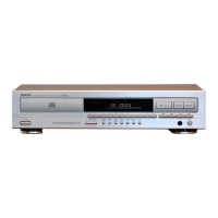
Identifies and explains the main unit's power, disc loading, remote sensing, and display functions.
Details the functions of the open/close, number, +10, play, and pause buttons.
Explains stop, search, program, repeat, auto space, and edit functions.
Describes headphone jack, volume control, output terminals, and digital output jack.
Guides on connecting output terminals and digital output jacks to external equipment.
Instructions for opening/closing the disc holder, loading discs, and performing normal playback.
Details on playing specific tracks, checking programs, and programmed playback.
Explains repeat, pause, audible search, blank insertion, and track beginning search.
Describes how to activate and use the random playback mode for discs.
Explains time specification editing and the pick function for tape recording.
Covers link function for multiple discs and setting fade-out time.
Details manual fading, time fade, and searching for the disc's peak level.
Explains peak search operation and changing playback speed (pitch control).
Provides guidelines for handling, cleaning, and storing compact discs properly.
Instructions for inserting batteries and operating the remote control unit.
Details button functions, program mode, and track selection via remote.
Lists detailed audio performance metrics and disc format information.
Covers power, dimensions, weight, features, and remote control system specs.
Describes the laser pick-up components and the labeling system used for quality control.
Details the pin assignments for PD and Actuator & LD connectors.
Covers handling, laser diode safety, and actuator care instructions.
Addresses metal bearing, general handling, deterioration, and decision criteria.
Provides step-by-step instructions for disassembling the top cover, front panel, loader, and clamper arm.
Details how to start the service program and lists the necessary adjustment equipment.
Shows component locations and initial preset values for adjustment potentiometers.
Outlines the sequence of adjustments: tracking offset, focus gain, and offset recheck.
Step-by-step guide for adjusting the tracking offset using VR101.
Procedure for adjusting focus gain using VR102 with oscilloscope and oscillator.
Instructions for adjusting focus offset using VR103 to minimize pattern jitter.
Details on adjusting tracking gain and performing an offset adjustment check.
Explains how to activate, operate, and troubleshoot errors in Heat Run mode.
Lists the terminals of the CXA1081S IC and their primary functions.
Provides detailed descriptions of each terminal's function for the CXA1081S IC.
Lists the terminals of the CXD2500Q IC and their corresponding functions.
Provides detailed descriptions of each terminal's function for the CXD2500Q IC.
Lists the terminals of the CXA1372S IC and their corresponding functions.
Contains notes on parts ordering and lists for resistors, capacitors, and their characteristics.
Lists semiconductor devices (ICs, transistors) and resistors used on the P.W. Board.
Lists capacitors, other miscellaneous parts, and accessories supplied with the unit.
Provides reference numbers and names for parts used in the exploded views.
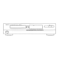
Shows an exploded view of the main unit with numbered part references.
Lists the part numbers and names for the FG-415/416 mechanism unit.
Presents an exploded view diagram of the FG-415/416 mechanism unit.
Illustrates the P.W. Board layout for the main unit (2U-2081 series).
Shows component placement on the main unit P.W. Board (2U-2082 series).
Diagrams showing the layout of key display units for DCD-860 models.
Diagrams showing the layout of key display units for DCD-660 models.
Illustrates the wiring connections between major units of the DCD-860 system.
Illustrates the wiring connections between major units of the DCD-660 system.
Provides diagrams and identification for ICs, diodes, and transistors used in the unit.
Presents the main schematic diagram for the DCD-860/660 unit.
Continues the main schematic and includes important notes on circuit and parts changes.
| Type | CD Player |
|---|---|
| Disc format | CD, CD-R, CD-RW |
| Digital converter | 24-bit/192 kHz |
| Channels | 2 |
| Frequency Response | 2 Hz - 20 kHz |
| Dynamic Range | 100 dB |
| Digital outputs | Coaxial, Optical |
| Channel separation | 95 dB |
| Output | 2.0V (fixed) |
| Line output | RCA |