EasyManua.ls Logo

Denon DCD-660 Service Manual

Denon DCD-660
42 pages
To Next Page IconTo Next Page
Page #1 background imageLoading...
Page #1 background image
DENON
__.......
SERVICE
MANUAL
STEREO
CD
PLAYER
MODEL
DCD-860/660
(Photo:
DCD-860)
TABLE
OF
CONTENTS
OPERATING
INSTRUCTIONS
SPECIFICATIONS
NOTE
FOR
HANDLING
OF
LASER
PICK-UP
DISASSEMBLY
ADJUSTMENT
HEAT
RUN
MODE
FUNCTION
iC
TERMINAL
FUNCTION
PARTS
LIST
OF
P.W.BOARD
PARTS
LIST
OF
PACKING
&
ACCESSORIES
PARTS
LIST
OF
EXPLODED
VIEW
EXPLODED
VIEW
PARTS
LIST
OF
FG-415/416
MECHANISM
UNIT
EXPLODED
VIEW
OF
FG-415/416
MECHANISM
UNIT
WIRING
DIAGRAM
SEMICONDUCTORS
SCHEMATIC
DIAGRAM
NIPPON
COLUMBIA
CO.
LTD.
Question and Answer IconNeed help?

Do you have a question about the Denon DCD-660 and is the answer not in the manual?

Denon DCD-660 Specifications

General IconGeneral
TypeCD Player
Frequency Response2 Hz - 20 kHz
Dynamic Range96dB
Total Harmonic Distortion0.003%
Signal to Noise Ratio110 dB
Output Level2.0 V
Channel separation98 dB
Digital OutputCoaxial
Power Consumption15 W
Disc formatCD

Summary

Safety and Warning Information

General Safety Precautions

Covers warnings about fire, shock, moisture, opening the unit, and internal objects.

Product Features and Capabilities

Laser Safety Warning Notices

Multilingual safety warnings regarding laser radiation exposure.

Component Identification and Controls

Front Panel Controls and Displays

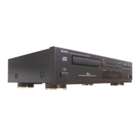
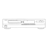
Identifies power switch, disc holder, remote sensor, display segments, and major playback buttons.

Component Identification and Functions

Connection and Basic Playback

Audio and Digital Output Connections

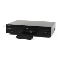
Explains how to connect the player's audio and digital outputs to an amplifier or processor.

Advanced CD Playback Functions

Programmed Playback and Management

Details how to program tracks, check programs, and clear programmed playback.

Remote Control Operation

Technical Specifications

Audio and Disc Performance Data

Specifications for audio channels, frequency response, dynamic range, distortion, and disc formats.

Laser Pick-up Handling and Maintenance

Laser Pick-up Component Identification

Identifies key components of the laser pick-up module.

Laser Pick-up Precautions and Diagnosis

Handling, Laser Diode, and Actuator Care

Guidelines for careful handling, laser diode protection, and actuator maintenance.

Deterioration Assessment and Testing

Methods for diagnosing laser pick-up deterioration based on voltage and current readings.

Disassembly Procedures

Adjustment Procedures

Service Program Activation and Functions

How to enter service mode, control buttons, and their functions during adjustment.

Adjustment Settings and Locations

Component Locations and Preset Adjustments

Identifies adjustment potentiometers and their initial preset positions.

Servo System Adjustments

Tracking Offset and Focus Gain

Step-by-step guide for adjusting tracking offset and focus gain using an oscilloscope.

Focus Offset Adjustment Procedure

Detailed instructions for adjusting the focus offset to minimize pattern jitter.

Tracking Gain and Offset Check

Procedures for adjusting tracking gain and performing an offset adjustment check.

Parts List - Printed Circuit Boards

Exploded View Diagram - Main Unit

Parts List - FG-415/416 Mechanism Unit

Exploded View - FG-415/416 Mechanism Unit

Printed Wiring Board Layouts

Wiring Diagram - DCD-860

DCD-860 Main Unit Wiring

Illustrates the overall wiring connections for the DCD-860 model.

Wiring Diagram - DCD-660

DCD-660 Main Unit Wiring

Illustrates the overall wiring connections for the DCD-660 model.

Schematic Diagram

Overall Circuit Diagram

A comprehensive schematic diagram detailing the unit's electronic circuitry.

Related product manuals