Do you have a question about the Denon DCD-1420 and is the answer not in the manual?
Guidelines for safe operation, installation, and servicing of audio equipment.
Features like Super Linear Converter and Digital Filter for sound quality.
Remote control, optical output, and 8cm CD playback capabilities.
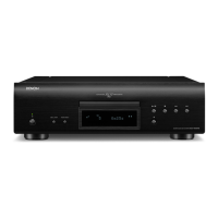
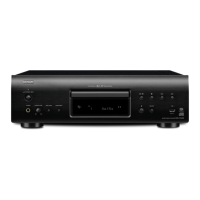
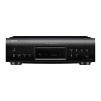
Description of essential parts like power switch, disc holder, and display.
Explanation of Auto Edit and Auto Space buttons.
Buttons for starting, stopping, pausing, and searching tracks.
Options for random, repeat, and programmed playback.
Buttons for direct track access, indexing, and display modes.
Jacks and controls for audio output level and headphones.
Connecting analog output terminals to an amplifier.
Connecting digital output jacks to processors or D/A units.
Procedure for opening, closing disc holder and loading discs.
Steps to begin CD playback.
How to stop the CD playback.
Direct track search, advancing, and returning to tracks.
Finding and playing sections within a track via index numbers.
Programming and playing tracks in a specific order.
How to clear the programmed track list.
Functions for repeating all tracks, single track, or intervals.
Temporarily halting playback and performing audible quick search.
Performing forward and reverse search within tracks.
Inserts silent gaps between tracks during playback.
How to set up and use timer-controlled playback.
Guidelines for handling, cleaning, and storing compact discs.
Tips to avoid interference with other electronic devices during installation.
Procedures for inserting batteries and operating the remote control.
Resolving problems with playback, disc condition, program setup, and remote operation.
Troubleshooting issues related to cable connections and amplifier settings.
Details on audio performance, general characteristics, and discs.
Information on remote control and supplied accessories.
Details on the components of the laser pick-up assembly.
Pin assignment for the Photodiode connector.
Pin assignment for the Laser Diode and Actuator connectors.
Precautions for storing and preventing physical damage to the pick-up.
Safety measures for the laser diode, including eye protection and surge protection.
Handling advice for Actuator, Metal Bearing, and general handling.
Identifying and deciding on pick-up deterioration.
Steps to remove the top, bottom, and front covers.
Steps to remove the loader mechanism, clamp arm, and main unit.
Steps to start the service program for adjustments.
Overview of buttons and their functions within the service program.
Preparations and tools required before starting adjustments.
Identifying the location of adjustment points on the main unit.
Setting initial values for adjustment potentiometers (VR101-VR105).
Adjusting the PLL volume VR105 for frequency counter reading.
Adjusting VR101 for tracking offset using an oscilloscope.
Adjusting VR102 to symmetrize Lissajous figures on oscilloscope.
Adjusting VR103 to minimize pattern jitter on oscilloscope.
Adjusting VR104 to symmetrize Lissajous figures on oscilloscope.
Verifying the tracking offset adjustment.
Activating and operating the Heat Run Mode.
Performing chucking and sound skipping tests.
Detailed functions of each terminal for the CXA1081S IC.
Detailed explanation of each terminal's function on the CXA1081S IC.
Detailed explanation of each terminal's function on the CXA1182AS IC.
Functional block diagram of the CXA1182AS IC.
Functional block diagram of the CXD1125Q IC.
Detailed explanation of each terminal's function on the CXD1125Q IC.
Further details on terminal functions for the CXD1125Q IC.
List of ICs, transistors, and diodes used on the PCB.
List of capacitors and resistors used on the PCB.
List of components for the 2U-1753 Display Unit.
List of components for the 2U-1754 series Power Supply Units.
Parts for miscellaneous items and the digital signal unit.
Reference numbers and names for parts shown in the exploded view.
List of items included for packaging and accessories.
List of parts for the FG-402 mechanism unit.
Diagram showing electrical connections between main units and components.
Layout diagram of the P.W. Board for the Servo & Signal Unit.
Layout diagrams for Display and Power Supply Unit P.W. Boards.
Diagrams and identification for ICs, transistors, and diodes.
Comprehensive schematic showing all circuit connections and components.
| Type | CD Player |
|---|---|
| Frequency Response | 2 Hz - 20 kHz |
| Total Harmonic Distortion | 0.0025% |
| Output Level | 2.0 V |
| Disc format | CD |
| Channel separation | 105 dB |
| Dimensions | 434 x 115 x 320 mm |
| Digital outputs | Coaxial |
| Line output | RCA |