20
20DN-C680
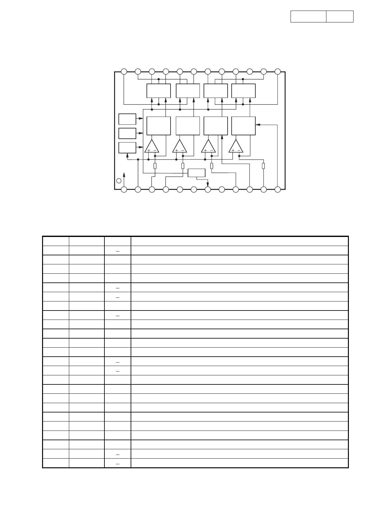
AN8389 (MA: IC111)
AN8389 Terminal Function
PVCC2
PGND2
D
4+
D
4
-
D3+
D
3
-
D2+
D
2
-
D1+
D
1
-
PGND1
PV
CC1
V
CC
VREF
IN4
IN3
GND
NC
VRESET
GND
IN2
PC2
IN1
PC1
BLT Linear
Driver
ch4
BLT Linear
Driver
ch3
BLT Linear
Driver
ch2
BLT Linear
Driver
ch1
Absolute
V
-
I
Direction
Det
Absolute
V
-
I
Direction
Det
Absolute
V
-
I
Direction
Det
Absolute
V
-
I
Direction
Det
thermal
Protect
Vcc
Monitor
VREF
Monitor
RESET
ch4 ch3 ch2 ch1
123456
7
8
9
24
23
22
21
20
19
18
17
16 15 14 13
12
11
10
Pin No. Symbol I/O Function
1 Vcc Power supply.
2 VREF I VREF input terminal.
3 IN4 I Motor driver 4 input terminal.
4 IN3 I Motor driver 3 input terminal.
5 GND GND.
6NC
7 NRESET O Reset output terminal.
8 GND GND.
9 IN2 I Motor driver 2 input terminal.
10 PC2 I PC2 (Power cut) input terminal.
11 IN1 I Motor driver 1 input terminal.
12 PC1 I PC1 (Power cut) input terminal.
13 PVCC1 Power supply terminal 1 for driver.
14 PGND1 GND terminal 1 for driver.
15 D1
-
O Motor driver 1 reversal output terminal, spindle motor drive.
16 D1+ O Motor driver 1 obverse output terminal, spindle motor drive.
17 D2
-
O Motor driver 2 reversal output terminal, tracking actuator drive.
18 D2+ O Motor driver 2 obverse output terminal, tracking actuator drive.
19 D3
-
O Motor driver 3 reversal output terminal, focus actuator drive.
20 D3+ O Motor driver 3 obverse output terminal, focus actuator drive.
21 D4
-
O Motor driver 4 reversal output terminal, slide motor drive.
22 D4+ O Motor driver 4 obverse output terminal, slide motor drive.
23 PGND2 GND terminal 2 for driver.
24 PVCC2 Power supply terminal 2 for driver.