EasyManua.ls Logo

Denon TU-580RD User Manual

Denon TU-580RD
22 pages
To Next Page IconTo Next Page
Page #1 background imageLoading...
Page #1 background image
INHALTSVERZEICHNIS
PEMIENUNGSAN
LE
NG
ore
ee
eee
igen
he
ate
AE
a
ae
a
alo
Se
eid
|B
Gite,
aR
Se
ale
ate
2~6
ENTFERNEN
DER
EINZELNEN
BAUGRUPPEN
...
2.
ee
eens
G
SUS
HE
OUING
we
rhe
Se
ech
ene
il
oe
ee
a
oe
Cee
aay
eRe
a
aut
Hew
aetee
a4
Bg
Bl
OC
KDIAGRAMM
=e
a
Oe
ee
ee
a
el
ee
ee
Ee
RW
ae
ees
ee
9
PANU
RE
SIP
ee
eee
ef
ee
ary
Be
et
eee
hh
eae
eee
w
te
eee
a
ete
s
10~14
ANKIERKUNGEN
ZUR
EILELIS
TE:
aeeiy
dee
bias
hie
i
ae
Sg
dint
Sa
ee
adeeb
aaa
ee
aa
te
se
eee
1
TEILELISTE
DER
PLATINE:
(1U-2506)
HAUPTEINHEIT.
2.02.0
ee
ees
15
~
16
PLATINE
(10-2506)
TUNEREINHEN
065.
Pete
ee
oes
Bn
te
oe
TE
A
ee
eee
eee
Aes
ed
EXPLOSIONS
ZEICHUNUNG.
isso
Se
ee
ek
Cele
ooh
eee
TAM
Sika
ee
eat
18
TEILELISTE
ZUR
EXPLOSIONSZEICHNUNG
220
ne
ee
een
nee
19
TRILELISTE
FUR
VWERPACKUNG
UND
ZUBEHOR?
ooh
breach
Cd
Se
ee
cae
de
Mei
ee
eee
19
ANSCHUUSSOIGAN
a
2
ce
seb
ee
ee
a
ee
ee
ee
Ce
ee
Re
Pea
Peay
ee
Ree
eee
20
SCHALTPLAN
ee
re
Pe
eng
Da,
ade
Se
hee
era
21
NIPP'
fe,
cio
po
aca
een
nner
stcsanetient
ier
atten
entry
Question and Answer IconNeed help?

Do you have a question about the Denon TU-580RD and is the answer not in the manual?

Denon TU-580RD Specifications

General IconGeneral
BrandDenon
ModelTU-580RD
CategoryTuner
LanguageEnglish

Summary

Safety and Usage Precautions

General Safety Warnings

Important safety instructions to prevent electric shock, fire, or damage.

Usage Environment Guidelines

Advice on operating conditions, temperature, moisture, and dust exposure.

Regional Compliance Statements

Notes on conformity for European and UK models.

Connection Diagrams and Accessories

Antenna Connection Guide

Illustrates connection of AM and FM antennas, including coaxial cable.

Included Accessories List

Lists all items included with the main unit in the carton across multiple languages.

Component Identification and Functions

Front Panel Controls and Indicators

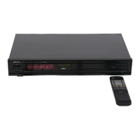
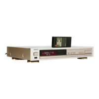
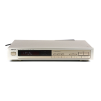
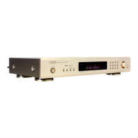
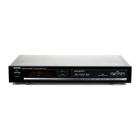
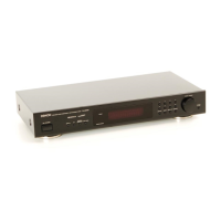
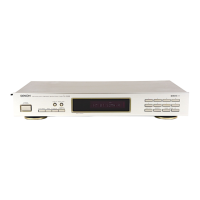
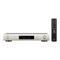
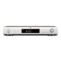
Describes the functions of front panel components like power and remote sensor.

Rear Panel Connections

Identifies and explains the rear panel terminals and their functions.

Power Standby Mode Operation

Explains the behavior of the power switch in standby mode and remote operation.

Unit Operation and Features

Display Indicators Explained

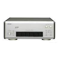
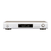
Details the meaning and function of various indicators on the display.

Using Tuning and Memory Functions

Instructions for selecting and storing channels, and using tuning buttons.

Remote Control Unit Functions

Explains how to use the remote control for functions like RDS and PTY search.

Remote Control Operation and Technical Specifications

Remote Control Usage Guidelines

Instructions for inserting batteries and proper operation of the remote control.

Technical Data - FM Reception

Specifies technical performance data for the FM receiver section.

Technical Data - AM Reception and General

Provides technical specifications for AM reception and other general data.

Disassembly Procedures

Removing the Top Cover

Step-by-step guide to remove the upper cover of the unit.

Detaching the Front Panel Assembly

Instructions for disconnecting wiring and removing the front panel.

Removing Internal Circuit Boards

Detailed steps for removing various circuit boards from the unit.

Instrument Adjustment Procedures

FM Alignment Points

Illustrates measurement points and required equipment for FM alignment.

AM Alignment Points

Shows test points and tools needed for AM alignment.

Alignment Settings

FM Alignment Settings

Table detailing specific settings for FM tuning alignment.

AM Alignment Settings

Table outlining the parameters for AM tuning alignment.

System Block Diagram

Tuner Unit Block Diagram

Schematic representation of the tuner unit's internal signal flow.

Semiconductor Component Details

Integrated Circuit (IC) Pin Assignments

Detailed pin descriptions for various ICs used in the unit.

Remote Control ICs and Support Components

Pin configurations for ICs related to the remote control and display.

Component Identification (Continued)

Additional IC and Voltage Regulator Details

Pin assignments and functional descriptions for more ICs and voltage regulators.

IC Protection and Series Information

Details on IC protection features and series characteristics.

Electronic Component Breakdown

Transistor and Diode Identification

Lists transistors and diodes with their pinouts and types.

Varactor Diode and Zener Diode Information

Details on varactor and zener diodes used in the circuit.

Remote Receiver and Display Connections

Remote Receiver Module (SBX1610-52)

Explains connections and pinouts for the remote receiver unit.

FL Display Module and Wiring

Details connections and wiring for the FL display.

Parts List - Main P.C.B.

Notes on Parts List Interpretation

Important notes for ordering parts and understanding the list.

List of Semiconductors

Identifies semiconductors (ICs, transistors, diodes) used on the main board.

List of Resistors and Capacitors

Enumerate resistors and capacitors with their specifications.

Parts List - Components and Connectors

Continued Component Listings

Lists remaining resistors, capacitors, and other electronic components.

Other Components and Connectors

Details crystal oscillators, filters, switches, and various connectors.

Tunner P.C.B. Schematic

Main Tuner Circuit Diagram

Detailed schematic of the main tuner printed circuit board.

Exploded Assembly Diagram

Unit Disassembly and Reassembly View

Visual representation of how the unit is assembled and disassembled.

Parts Lists and Accessories

Parts for Exploded View

Lists parts corresponding to the exploded view diagram.

Packaging and Included Accessories

Details the packaging materials and accessories supplied with the unit.

Internal Connection Plan

Module Interconnection Diagram

Shows how different internal modules are connected to each other.

Circuit Schematics and Safety

Main P.C.B. Circuit Schematic

Detailed schematic for the main printed circuit board.

Display and Key Matrix Schematics

Schematics for the display and key matrix printed circuit boards.

Critical Component Safety Notes

Warnings regarding critical components and safety checks.

Circuit Schematics (Continued)

Further Circuit Diagrams

Continuation of detailed schematics for various circuit boards.

Operational Safety Checks

Important safety procedures and checks before returning the unit to the customer.

Related product manuals