8. Dipswitch
On the PCB, you will nd a 8-pol DIPSWITCH row:
The function of these 8 DIPSWITCHES:
SW 1 = ON = SHOOT verication relay active
SW 2 = ON = Front LED’s are OFF
SW 3 = ON = Internal Buzzer turned OFF
SW 4 = ON = All output relay in Active Security (*)
SW 5 = ON = PANIC function enabled
SW 6 = ON = Active input on ARM and SHOOT (NC)
SW 7 = Not used
SW 8 = ON = Fog generator in SERVICE mode
(Active Security means that all relay’s are electrically
activated in rest position).
IMPORTANT:
When changing position on the dipswitch, you need to
turn OFF the power, wait 20 seconds and then turn ON the
power again, to make the change work.
EXCEPTION: Dipswitch 8, Service mode, works instantly.
When you turn dipswitch 8 ON, the fog generator will
enter SERVICE MODE, where all functions have been
disabled. When turning dipswitch 8 OFF again, the fog
generator will enter normal mode again.
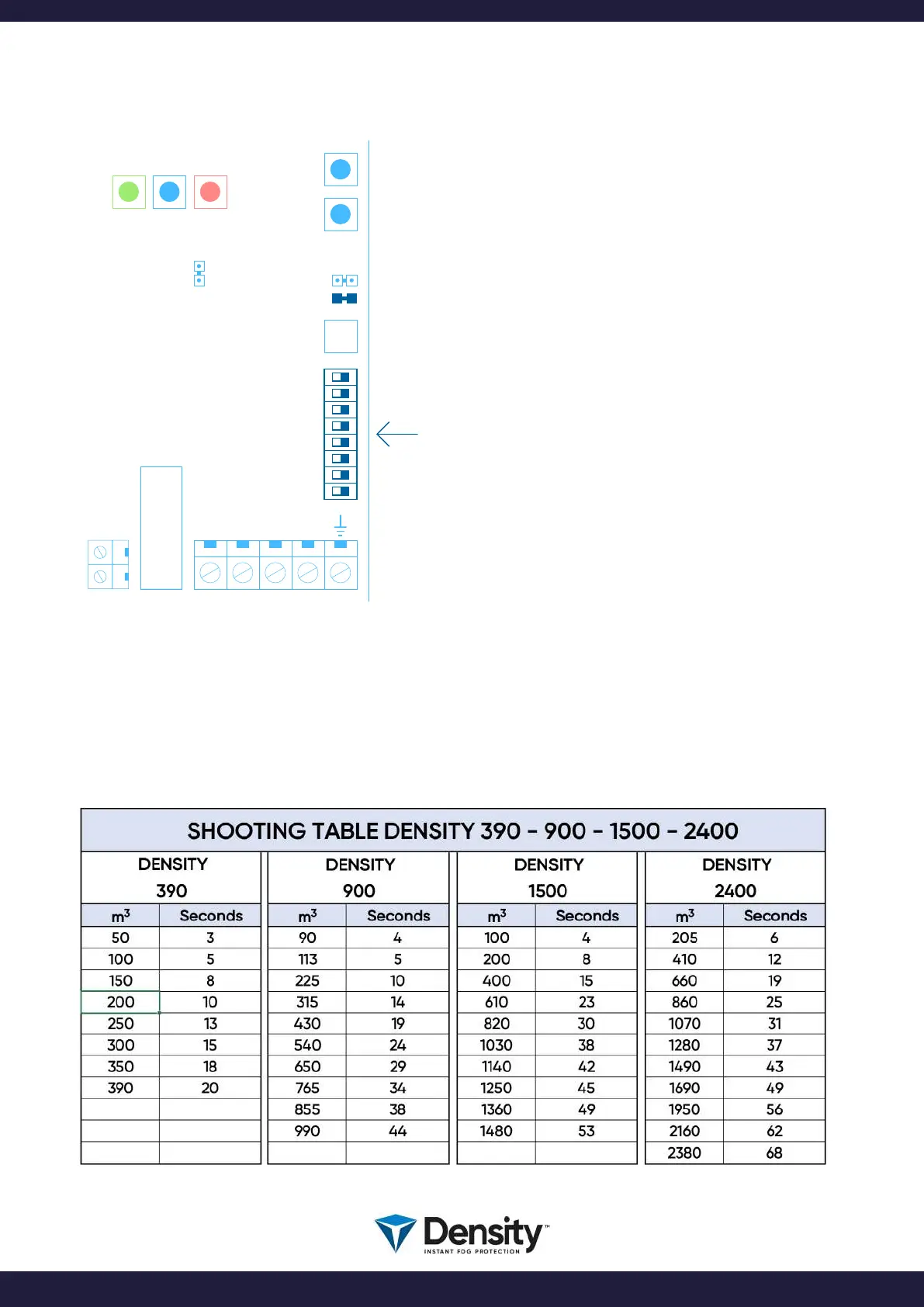
The fog generator can be programmed to SHOOT fog in a dened number of seconds, when the
activation of the fog machine has been done.
Find the proper time setting, by calculating the room volume, and nd the equivalent time in these tables:
BOOT
USB
C PLUS PCB
W2
W1
N
L
FIRETIME
RESET
MAINS
FUSE
F4
1
2
3
4
5
6
7
8
ON OFF
9. Shooting Time Setting
page 14/20
www.densityglobal.com | help@densityglobal.com
Version 1.1.4