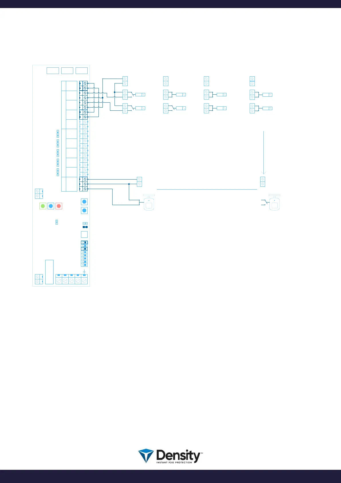
6.2.1 Connection diagram examples
(VERIFICATION SENSOR)
COM 3COM 2COM 1
W3
NO
NC
W4
NO
NC
W5
NO
NC
W6
NO
NC
W7
NO
NC
USB
C PLUS PCB
W2
W1
N
L
FIRETIME
ACTION DAYTIME ACTION NIGHTTIME
INTRUDER SYSTEM DISARMED
FOG GENERATOR DISARMED
RESET
0V
ARM
PRIMARY TRIG
+ 12V
0V
+ 12V
PIR SENSOR
STATUS NOT ACTIVATED
IMPORTANT!
JUMPER W1 MUST BE INSERTED
FOR ENABLING PIR FUNCTION
MAINS
FUSE
F4
PIR SENSOR
STATUS ACTIVATED
INTRUDER SYSTEM ARMED
FOG GENERATOR ARMED
INTRUDER SYSTEM IN ALARM
FOG GENERATOR ARMED
FOG GENERATOR READY TO SHOOT FOG
(WAITING FOR THE PIR SENSOR)
0V
ARM
+ 12V
0V
ARM
ALARM TRIG
+ 12V
1
2
3
4
5
6
7
12V OUTINPUTOUTPUTPIR
+ 12V
GND
ARM +
ARM -
TRG +
TRG -
IN 0 +
IN 0 -
IN 1 +
IN 1 -
EMPC
EMP
FLTC
FLT
TMPC
TMP
FVLC
FVL
AUXC
AUX
PIR +
PIR -
PIRC
ACTION ALARM
BOOT
PRIMARY TRIG
INTRUDER SYSTEM IN ALARM
FOG GENERATOR ARMED
VERIFICATION PIR SIGNAL ACTIVE
FOG GENERATOR SHOOTING
0V
ARM
ALARM TRIG
+ 12V
ACTION ALARM + VERIFICATION
0V
+ 12V
DIPSWITCH 6 MUST BE TURNED OFF
TO ENABLE NO (Normal Open) ACTION
DIPSWITCH 8 MUST BE OFF TO
ENABLE NORMAL OPERATION MODE
8
ARM, VERIFY and SHOOT:
To control the fog generator, you use the ARM input on the fog generator. When you ARM the fog
generator, it will be ready to SHOOT when it is HOT (Green LED must be on and STEADY).
When you ARM the fog generator, the Blue LED will come on steady. Now the fog generator is ready and
Armed.
The 2’ input «IN 0» in this diagram, is hardwired and thereby always active.
For SHOOT (when Ready and ARMED), you activate the TRG input, AND you activate the PIR input.
Shooting will happen when BOTH inputs are triggered at the same time.
Shooting time as set on the SHOOT-timer.
page 9/20
www.densityglobal.com | help@densityglobal.com
Version 1.1.4