16788-InstructionSheet
Derale Performance, Los Angeles, 323.266.3850 www.derale.comCA
INSTALLATION INSTRUCTIONS
ADJUSTABLE DUAL ELECTRIC FAN CONTROLLER
PART # 16788
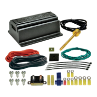
KIT CONTENTS
Please read these instructions completely before beginning installation
TOOLS NEEDED
Drill
5/32” Drill Bit
Teflon Tape
12V Test Light
Standard Screw Driver
or a 5/16” Nut Driver
Standard Screw Driver
(1/8” wide blade)
Wire Stripper
Wire Crimping Tool
CONTROL MODULE INSTALLATION
1. Choose a convenient location, preferably along the vehicles core support
near the battery. Take in to consideration probe placement & wire routing
requirements. Avoid mounting near engine components or a locationHOT
that would be in direct contact with any road debris.
2. Using the module as a template, mark and drill four 5/32” holes in the
proper location.
3. Using four #10 sheet metal screws supplied, secure the unit in place.
CIRCUIT BREAKER MOUNTING
1. Choose a convenient location for the Circuit Breaker that is between the
Dual Fan Controller and the Battery.
2. Using the breaker as a template, mark and drill two 5/32” holes in the
proper locations.
3. Using the remaining two #10 sheet metal screws supplied, secure the
Circuit Breaker in place.
THERMOSTAT PROBE INSTALLATION
Placement: For best results we recommend installing the probe as close
as possible to the water inlet of the radiator.
Installation:
1. Take the Push-in Probe and thread it clockwise onto the Brass Sensor
Housing.
2. Carefully insert the probe assembly into the fins of the radiator until
Sensor is flush with radiator.
3. Install the 1 x 1 Foam Pad onto the Push-in Probe.
4. Install Retaining Clip onto the Push-in Probe until tight. (See Dia. #3)
WIRING
Before starting, disconnect the Negative (-) cable on the vehicles battery.
Using the electrical connectors and wire ties provided, follow the instructions
below. (See Diagram #4 on reverse side)
Red Wire (harness side): To Positive (+) 12v Battery
1. Using the Yellow 5/16” Ring Terminal & 10 Ga. Red Wire supplied,
connect one end of the red wire to the vehicles Positive (+) terminal on
the battery.
2. Route the 10 Ga. Red Wire now connected to the battery to the Circuit
Breaker previously installed and cut the wire to the appropriate length.
3. Using a Yellow #10 Ring Terminal, connect the 10 Ga. Red Wire to the
“ ” Terminal on the Circuit Breaker.BAT
4. Using a Yellow #10 Ring Terminal, connect the auxiliary side “ ” of theAUX
circuit breaker to another length of 10 Ga. Red Wire.
5. Route the 10 Ga. Red Wire now connected to auxiliary side of the circuit
breaker to the Red Wire (harness side) located on the Dual Fan
Controller and cut the wire to the appropriate length.
Diagram #1
This unit utilizes an auto resetting circuit breaker to protect the fans
and controller circuit. In the event of an electrical short, the breaker
will “trip” and open the connection between the battery and the
controller. If this happens, turn the vehicle off and let it cool before
restarting the system. The breaker will automatically reset.
IMPORTANT
WARNING
HOW IT WORKS
The Derale High Amperage Adjustable Dual Fan Controller is designed to
operate two electric fans at different activating temperatures. Fan #1 is
designed to activate at the desired adjusted temperature (150°F-240°F).
Fan #2 will activate once the vehicle water temperature increases by 15°F.
The fans will deactivate 10°F below each turn-on temperature.
This unit is designed to control 2 electric fans with a
Maximum Draw of 35 Continuous Amps Per Fan.
This controller using the followingWill Not Work
2-speed O.E. Electric Fans: Dodge Viper, Ford Taurus,
or Lincoln Mark . These fans exceed the amperageVIII
& functionality capabilities of this fan controller.
For proper installation the control module must be
mounted within 5 feet of the vehicle's battery.
Diagram #2
Push-in
Radiator Probe
Water
Inlet
Water
Outlet
Push-in
Radiator
Probe
Cross-flow Radiator
Down-flow Radiator
(Wiring Continues on reverse side)
Water
Inlet
Rubber
Plug
Probe Wires
Battery (+)
Ground (-)
Adjustment
Screw
Fan 2 (+)
Fan 1 (+)
Ignition (+)
Override (+)
QTY DESCRIPTION.
1 Adjustable Dual Fan Controller
1 Push-in Probe
1 Foam Pad
1 Retaining Clip
1 50 Amp Circuit Breaker
1 6ft 10Ga. Red Wire
QTY DESCRIPTION.
6 #10 Sheet Metal Screw
5 Yellow Butt Connector
2 Yellow #10 Ring Terminal
1 Yellow 5/16” Ring Terminal
2 Blue Wire Tap Connector
4 4” Wire Ties
1 Red #10 Ring Terminal
Radiator
Foam Pad
Retaining
Clip
Push-in
Probe
Thermostat
Sensor
Diagram #3
Rev. 05142018