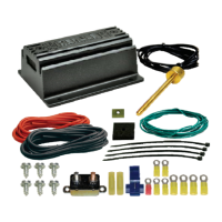
Please direct all technical questions to our Derale tech line at (800) 421-6288
VEHICLE TESTING
1. Before you start the vehicle, make sure all wires are safely zip tied and away from any moving parts.
2. Start the vehicle.
3. If the Manual Override function is being used, turn on the A/C or Manual Switch. Electric Fan(s) should start running
immediately.
4. Turn off the Manual Override or A/C function & allow the engine to warm up.
6. Route the Red 10 wire now connected to the auxiliary side of the circuit breaker to the Positive (+) Battery Terminal andAWG
connect using a Yellow #6 Ring Terminal.
7. Using the Red 10 wire and a Yellow #6 Ring Terminal, connect into the positive (+) Fan Terminal on the Control Module.AWG
8. Using a Yellow Butt Connector, connect the loose end of the Red 10 wire connected to the positive (+) Fan Terminal to theAWG
positive (+) side of the fan(s).
9. Using a #6 Yellow Ring Terminal, connect the 10 Black wire to the Negative (-) Terminal on the Control Module. Route theAWG
other end of the wire to the Negative terminal on the vehicles battery. Do not connect to a chassis ground.
WIRING
Before starting, disconnect the Negative (-) cable on the vehicles battery.
Using the electrical connectors and wire ties provided, follow the instructions on the next
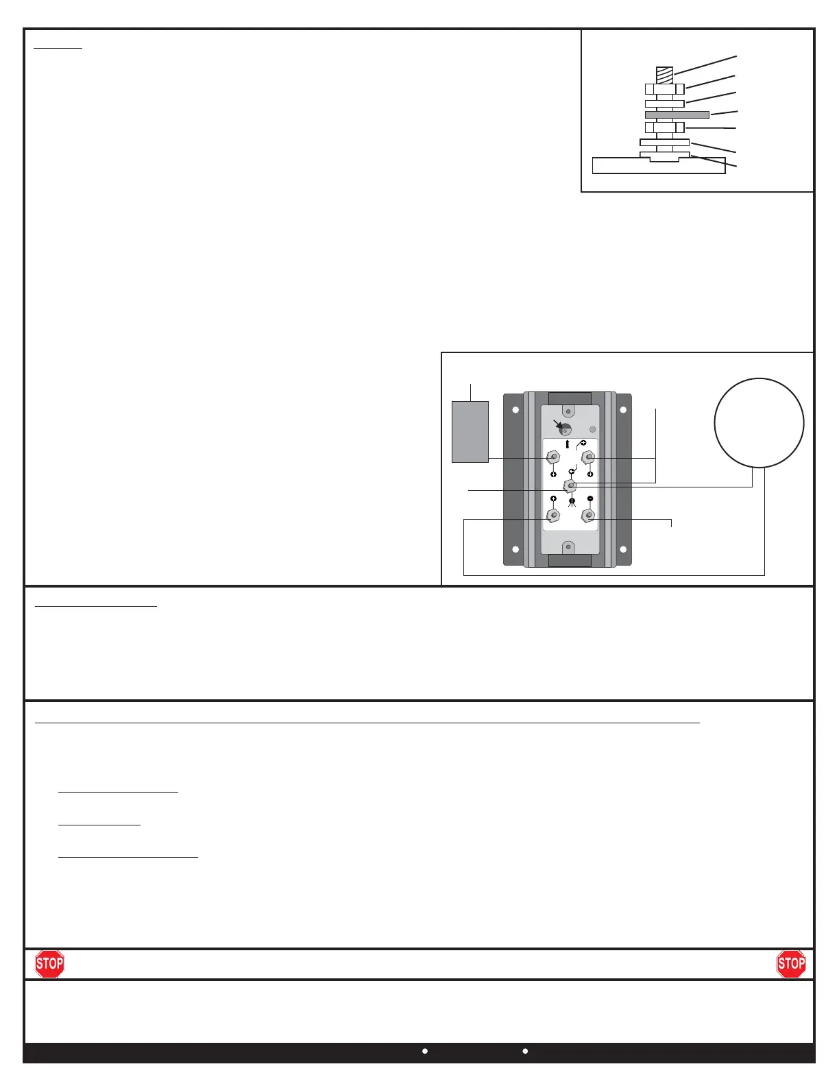
page. (See Dia. #3 for proper lug stacking)
1. Using a 3/32” Allen Wrench, remove the Control Module cover.
2. Using a Yellow #10 Ring Terminal & 10 Red Wire supplied, connect one end of theAWG
red wire to the vehicles Positive (+) terminal on the battery.
3. Route the 10 Red Wire now connected to the battery to the Circuit BreakerAWG
previously installed and cut the wire to the appropriate length.
4. Using a Yellow #10 Ring Terminal, connect the 10 Red Wire to the “ ” TerminalAWG BAT
on the Circuit Breaker.
5. Using a Yellow #10 Ring Terminal, connect the auxiliary side “ ” of the circuit breakerAUX
to another length of 10 Red Wire.AWG
10. Using a Yellow Butt Connector, connect the 10 Black wire toAWG
the Negative (-) lead of the fan(s). Route the other end of this
wire to the fan (-) terminal of the Control Module.
Green Wire: Override Circuit (Optional)
The green wire is designed to work in two different configurations.
When used, this will allow the Electric Fan(s) to be turned on
regardless of the temperature of the Sensor. The fan speed will
quickly ramp up to 60% and will operate between 60% and 100% as
temperature fluctuates. Use of the Override terminal is optionalNote:
and not required for the controller to work properly.PWM
1. A/C Override - Using the provided, attachBlue Wire Tap Connector
the green wire to a Positive (+) 12V output on the compressor.A/C
2. Manual Switch Override - Attach the Green Wire to the 12V output
on the manual switch (not provided).
Warning: Installation of accessories should only be undertaken by those with mechanical knowledge and are familiar with working on vehicles.
Always use eye protection (goggles, safety glasses or shield). Park the vehicle in a well lit area, on level ground and apply the parking brake. Only
work on a cold vehicle that has been sitting overnight, failure to do so will result in severe burns and injury. Before starting the vehicle, make sure no
tools or any other items are left under hood that could interfere with or be drawn into moving parts of the engine. Failure to follow instructions can lead
to severe damage and personal injury.
Derale Performance, Los Angeles, 800.421.6288 www.derale.comCADerale Performance, Los Angeles, 800.421.6288 www.derale.comCA
Diagram #4
DERALE PERFPORMANCE
SENSOR
OVERRIDE
BATTERY
SENSOR
FAN
BATTERY
CALIBRATION
POTENTI OMETE R
MULTIMETER
FAN
S
S
( )
A
C
U.S. PATENT 7006762 - MADE IN U SA
S
( )
( )
B.AT
To Battery
12V (+)
Sensor
Two Wire
Circuit
Breaker
AUX.
Battery (-)
Fan (+)
Fan (-)
Override Circuit
12V (+)
Electric
Fan(s)
To Sensor
Adjustment
Screw
Flat Washer
Shoulder
Washer
Nut
Diagram #3
Nut
Split Washer
Terminal
Terminal
Troubleshooting - in the event the fan controller is not performing properly follow these tests in order:
1. Check that all wire splices are crimped properly and that all connections are solid.
2. Verify at least 12 volts to the Battery (+) terminal on the fan controller.
3. Test the fan(s) by wiring them directly to 12 volts (+) to make sure the fans in fact do work.
4. Use a jumper wire to connect the battery positive (+) post on the fan controller to the A/C override post.A/C Override Test:
This should turn on the fan(s) at 60% capacity. Pass, the fan controller is working as designed. Fail, call technical support.
5. Use a jumper wire to connect the sensor ground post (-) to the sensor positive post (+). This should turn onSensor Test:
the fan(s) 100%. Pass, the fan controller is working as designed. Fail, call technical support.
6. Remove the rubber cover and turn the potentiometer adjusting screw 25 FULL turns counter-Fan Controller Reset:
clockwise. This resets the fan trigger temperature to its lowest setting. If the fan(s) are turning on too early after bringing
engine up to operating temperature turn the potentiometer adjusting screw clockwise 2 FULL turns until the desired fan turn
on temperature is reached.
 Loading...