107304-01D
For more information, visit www.desatech.com
For more information, visit www.desatech.com
7
7
CAST IRON STOVE AND
DIRECT-VENT BURNER
SYSTEM ASSEMBLY
Continued
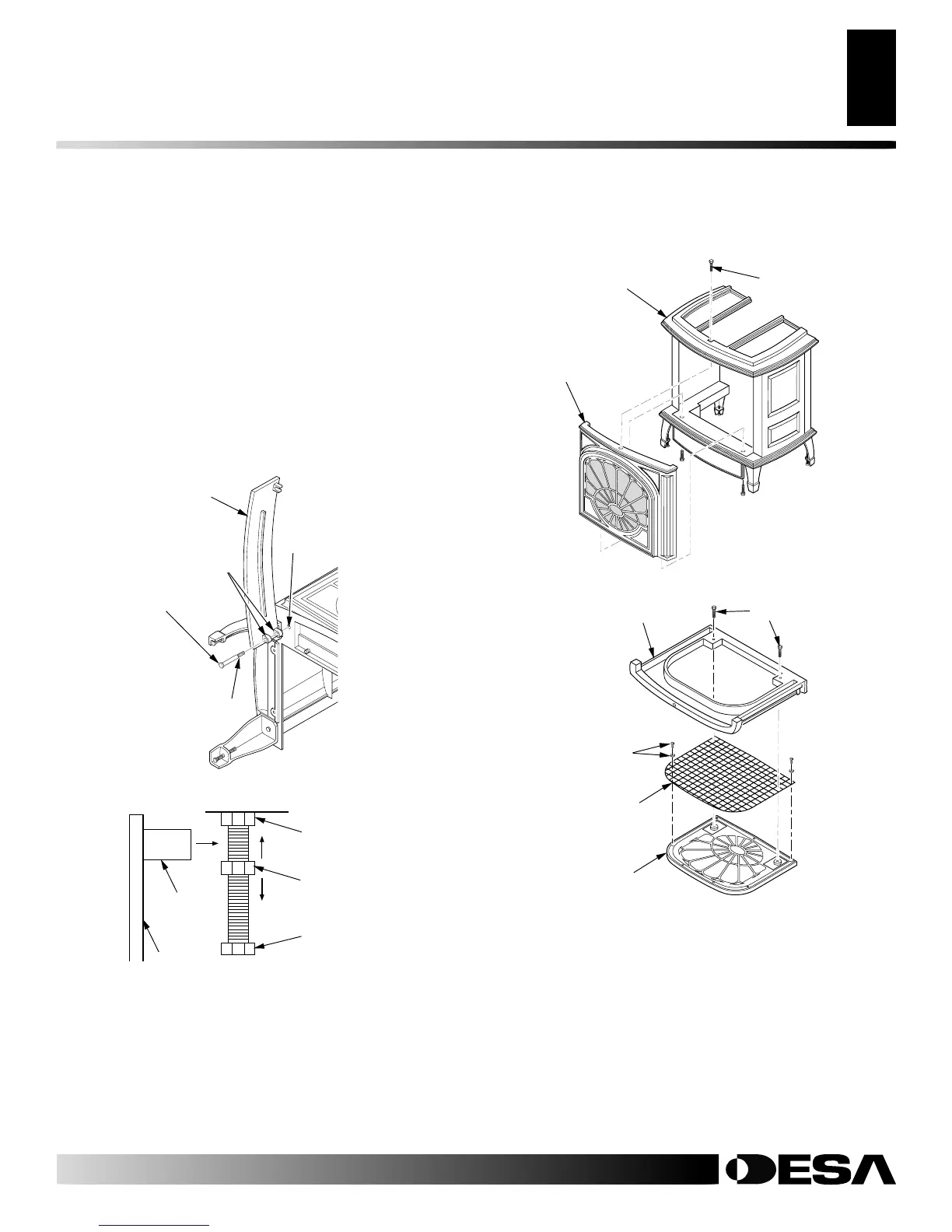
Adjusting Nut
Bolt Stop
Catch Bolt
Door Claw
Door
Figure 12 - Catch Bolt and Door Claw Orientation
14. Lay the front panel assembly face down on a protected sur-
face. Remove the two screws that hold the front plate onto the
front surround plate (see Figure 14). Save these screws.
15. Optional: Remove the seven screws and washers that hold the
screen onto the front surround plate. Discard these screws, wash-
ers, and screen. They are for vent-free use only (see Figure 14).
16. Replace the two screws from step 14 to reassemble the front
plate and the front surround plate. Set this assembly aside un-
til burner system has been installed, logs have been placed
inside of burner system, and glass door to burner system insert
has been replaced.
Figure 11 - Attaching Lower Stove Door Panel
Stove Door
Panel
Door Hinge
Step Bolt
Threaded
Hole
Bolt Shoulder
Figure 13 - Removing Front Assembly
Front
Assembly
Bolt
Stove
Body
Figure 14 - Removing Screen from Front Assembly
Screws
Front Surround
Plate
Front Plate
Screen
Screw with
Washer
CAST IRON STOVE AND DIRECT-VENT BURNER SYSTEM ASSEMBLY
Stove Body Assembly (Cont.)