www.desatech.com
116192-01M30
OPERATING OPTIONAL
GWMT1 - WALL MOUNTED
THERMOSTAT
WARNING: Do not con-
nect the thermostat to a power
source. Electrical shock and/or
a re hazard will occur.
Light the replace as instructed in Lighting
Instructions on page 27. Set wall thermostat
to desired temperature.
This thermostat has been electronically cali-
brated at the factory and requires no adjust-
ment or leveling.
Upon installation, the thermostat must be al-
lowed to stabilize at room temperature for a
minimum of 30 minutes for proper operation.
To turn the replace off, adjust thermostat to
the lowest setting and turn the gas control
knob back to PILOT. The pilot will remain lit.
IMPORTANT: To turn the pilot off, turn the
gas control knob on the heater to the OFF
position.
OPERATING OPTIONAL
BLOWER ACCESSORY
Locate the blower controls by opening the
lower louver panel on the replace. Blower
controls are located on the right side of the
switch bracket to the left just inside the louver
panel.
The BK manual blower and the BKT ther-
mostatically-controlled blower have an ON
setting and an OFF setting. The blower will
only run when the switch is in the ON posi-
tion. In the OFF position, the blower will not
operate.
Note for BKT Only: If you are using BKT blow-
er with optional thermostat (wall mounted or
remote control) for the replace, your replace
and blower will not turn on and off at the same
time. The replace may run for several minutes
before the blower turns on. After the heater
modulates to the pilot position, the blower will
continue to run. The blower will shut off after
the rebox temperature decreases.
The blower helps distribute heated air from
the replace. Periodically check the louvers of
the rebox and remove any dust, dirt or other
obstructions that will hinder the ow of air.
OPERATION
Continued
INSPECTING BURNERS
Check pilot ame pattern and burner ame
patterns often.
PILOT ASSEMBLY
The pilot assembly is factory preset for the
proper ame height. Alterations may have
occurred during shipping and handling. Call
a qualied service person to readjust the pilot
if necessary.
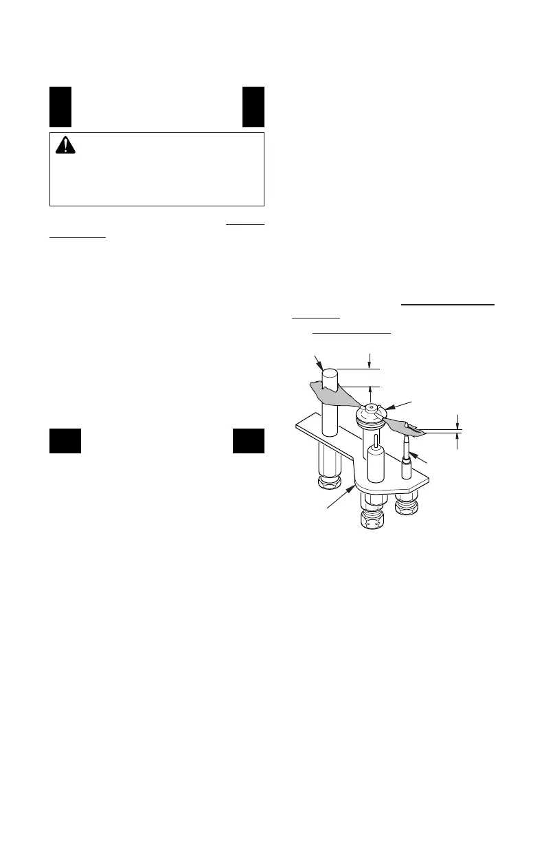
The height of the thermopile must be 3/8" to
1/2" above the pilot ame as shown in Figure
49. The thermocouple must be at a height of
about 1/8" above the pilot ame. The ame
from the pilot burner must extend beyond both
the thermocouple and thermopile.
If you pilot assembly does not meet these
requirements:
• turn replace off (see To Turn Off Gas to
Appliance, page 28)
• see Troubleshooting, page 33
Thermocouple
Thermopile
1/8"
Pilot Burner
Piezo Ignitor
Figure 49 - Pilot Assembly
3/8" to 1/2"
 Loading...