www.desatech.com
111986-01F6
PRE-INSTALLATION
PREPARATION
Continued
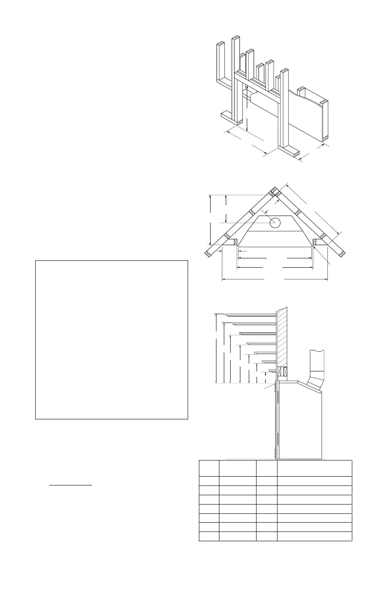
Figure 4 - Framing Clearances for
Installation Against an Exterior Wall
Figure 5 - Framing Clearances for Corner
Installation
C
B
A
D
E
F
G
T o p of Louver
Opening
3
2
1
4
5
6
7
Wall
Ref.
Mantel
Depth Ref.
Mantel from Top of
Louver Opening
1 14" A 16"
2 12" B 14"
3 10" C 12"
4 8" D 10"
5 6" E 8"
6 4" F 6"
7 2" G 4"
Figure 6 - Clearances for Combustible
Mantels
CLEARANCES
Minimum clearances to combustibles for the
replace are as follows:
*Back and sides 0"
Perpendicular walls 6"
Floor 0"
Ceiling to louver opening 42"
Front 36"
Top of Standoffs 0"
Vent (See venting instructions for
specic venting clearances.)
Combustible material with a maximum thick-
ness of 5/8" may be ush with the top front of
replace.
* For back and sides of replace, do not pack
with insulation or other materials. 0" clear-
ance to combustible materials are for framing
purpose only.
-
-
FRAMING AND FINISHING
Figure 4 shows typical framing of this replace.
Figure 5 shows framing for corner installation.
All minimum clearances must be met.
For available accessories for this replace,
see Accessories on page 36. If you are using
a separate combustible mantel piece, refer to
Figure 6 for proper installation height. You can
install noncombustible mantels at any height
above the replace.
Note: Noncombustible mantels may discolor!
32
3
/
8
"
34
5
/
8
"
19"
28
1
/
2
"
13
5
/
8
"
39
3
/
8
"
9
1
/
2
"
9
7
/
8
"
34
3
/
8
"
34
5
/
8
"
54
1
/
8
"
Nailing
Tabs
 Loading...