www.desatech.com
116662-01G 9
INSTALLATION
Continued
INSTALLING BLOWER ACCESSORY
(Model FB32CB Only)
You may install blower accessory GA3750A
with conventional installation (below) or with
built-in installation (page 11).
Conventional Installation of Blower
Accessory
NOTICE: If a log set is currently
installed in the rebox, disconnect
log set from gas supply and remove
from rebox. Contact a qualied
service person to do this.
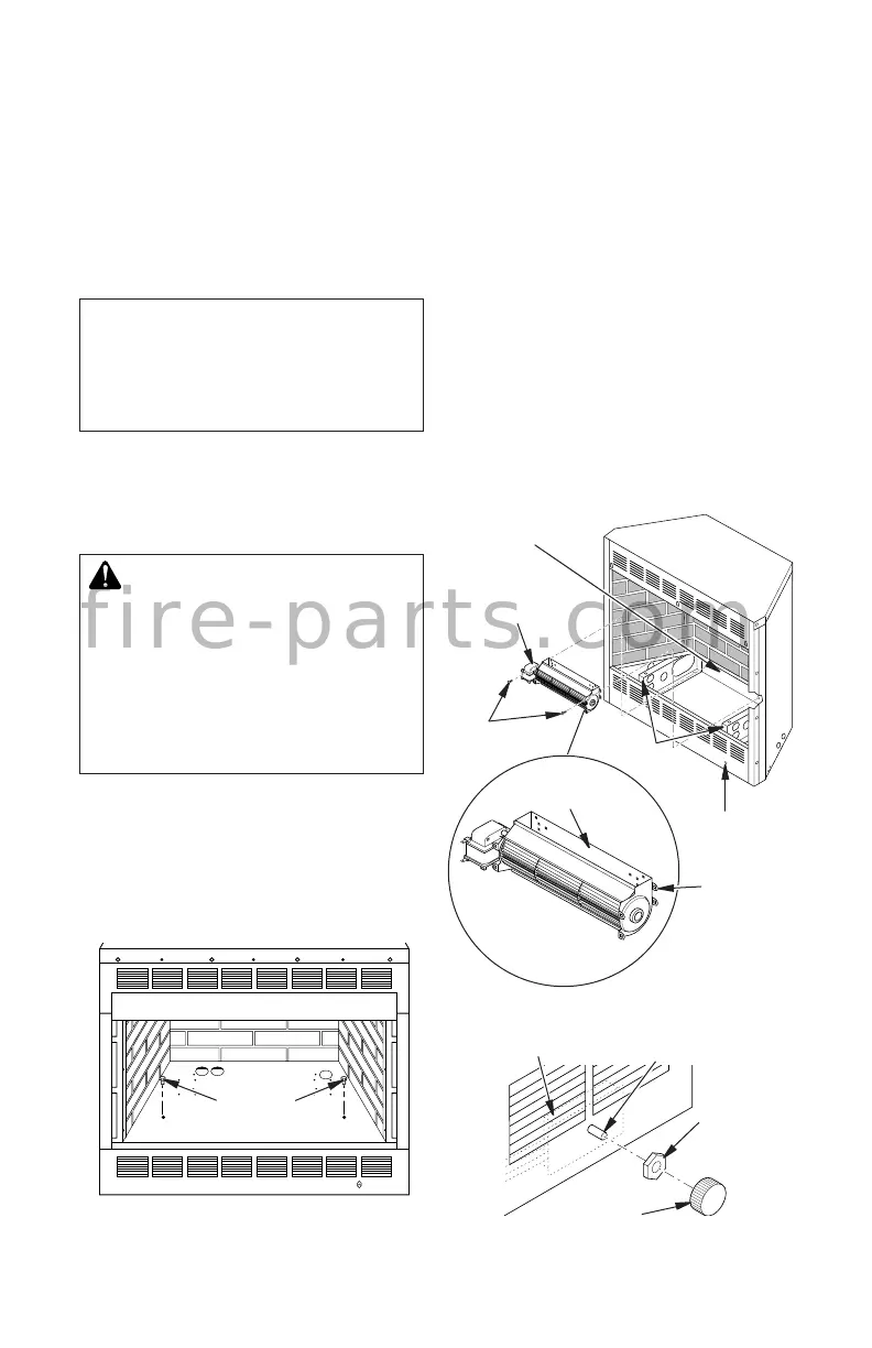
1. Remove rebox bottom:
a. Remove 4 screws that secure bottom
of rebox (see Figure 8).
b. Carefully raise and remove rebox bot-
tom from rebox.
WARNING: If there is a duplex
electrical outlet installed in the
right side of the bottom of the
replace base area, be sure that
the electrical power to the outlet is
turned off before proceeding with
blower installation. Failure to do
this may result in serious injury.
2. Place blower against lower rear wall of
rebox wrapper with exhaust port directed
upward. Align holes in top mounting tabs
of blower with holes in wall of wrapper
(see Figure 9). Using 2 screws provided,
mount blower and tighten screws se-
curely.
Figure 8 - Removing Screws from
Firebox Bottom
Screws
3. Be certain that all wire terminals are
securely attached to terminals on blower
motor and that the screw retaining green
ground wire is tight.
4. Locate plastic hole plug installed in the
3/8" diameter opening in the lower right
side of rebox front panel (see Figure 9).
Remove plastic plug and discard.
5. Place speed control against inner wall of
front panel, pushing plastic control shaft
forward through opening (see Figure 10).
6. While supporting speed control, secure
control shaft with lock nut by pushing and
turning lock nut with pliers clockwise until
it is tight against front panel. Place control
knob provided on shaft (see Figure 10).
Screws
Blower
Lower Rear
Wall of Firebox
Wrapper
Floor
Supports
Top
Mounting
Tab
Exhaust
Port
Plastic
Hole Plug
Figure 9 - Mounting Blower to Firebox
Figure 10 - Attaching Speed Control
Speed Control
Control Knob
Lock Nut
Control Shaft
f i r e - p a r t s . c o m