www.desatech.com
116662-01G10
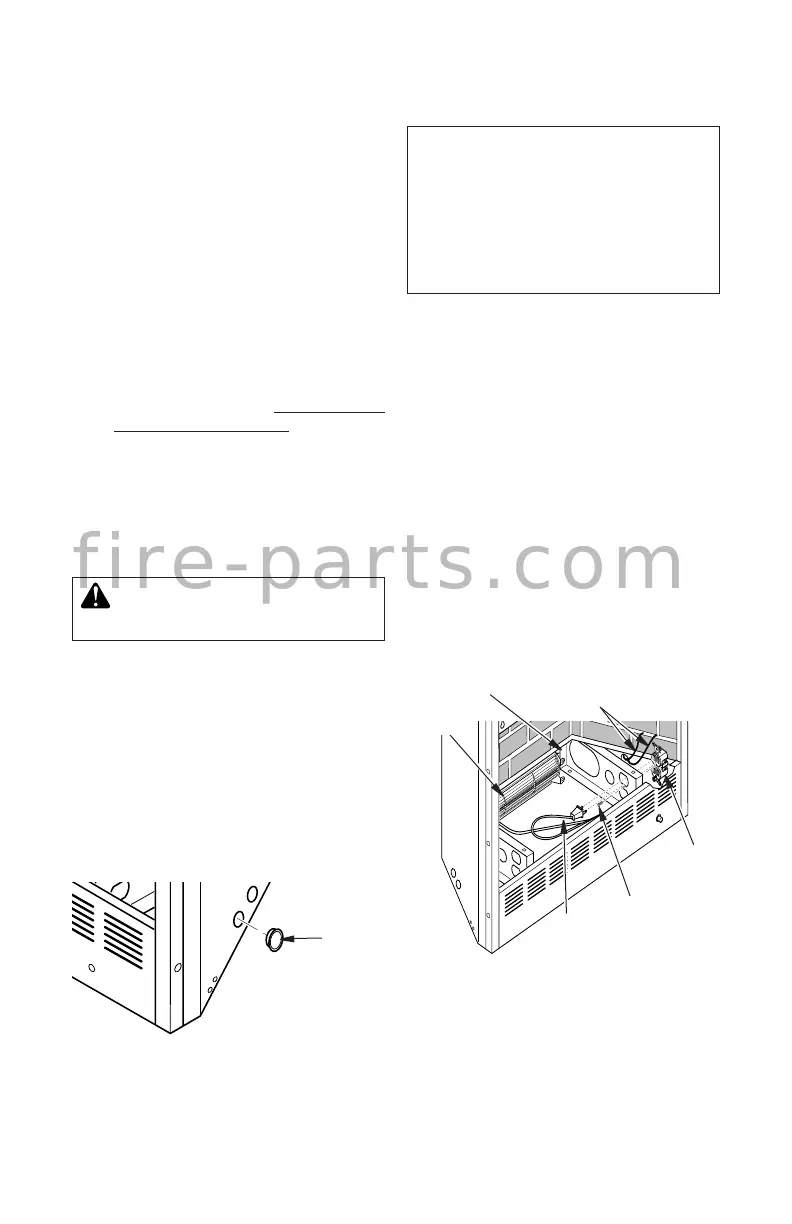
7. Plug in blower power cord.
a. If your rebox is installed as a freestand-
ing unit, determine whether power cord
will exit left side or right side of rebox.
Install 1 plastic bushing provided into
the 1
1
/
2
" hole in the oor support on the
exit side. Install second plastic bushing
(provided) into the 1
1
/
2
" hole in outer
casing through which power cord will
exit (see Figure 11). Route power cord
through both plastic bushings and plug
power cord into a 3-prong grounded
wall receptacle near rebox.
b. If your rebox installation is recessed
and/or pre-wired, see Built-In Installa-
tion of Blower Accessory, page 11.
8. Turn on power to duplex outlet if previ-
ously turned off per warning in step 1.
9. Check to make sure that power cord is
completely clear of blower wheel and
that there are no other foreign objects in
blower wheel. Turn blower on and check
for operation.
WARNING: Never touch the
blower wheel while in operation.
10. Peel off backing paper and stick supplied
wiring diagram decal on rebox bottom
approximately 12" in front of blower.
11. Replace bottom of rebox. Note: Make sure
back of rebox bottom slides under rear of
rebrick (lift rebrick up if necessary.)
12. Reattach rebox bottom using 4 screws
removed in step 1. Note: Discard remain-
ing hardware items.
13. Install log set heater according to instal-
lation instructions supplied with heater.
INSTALLATION
Continued
NOTICE: A qualied electrician
must connect electrical wiring to
duplex outlet for built-in instal-
lation. Follow all local codes. In
absence of local codes follow
The National Electrical Code
ANSI/NFPA 70.
Built-In Installation of Blower Accessory
1. Before replacing bottom of rebox, re-
move screw holding duplex outlet to sup-
port bracket in bottom of rebox. Remove
duplex outlet.
2. Clamp electrical cable into rebox through
smallest hole in outer casing using strain
relief provided.
3. Route wires from electrical box through
hole in side of heater and hole in support
bracket (see Figure 12).
4. Connect wires from the electrical box to
duplex outlet. Match wire colors to those
indicated on duplex outlet. Be sure to
connect ground wire.
5. Replace duplex outlet with screw.
6. Plug blower power cord into duplex outlet.
7. Replace bottom of rebox.
Figure 11 - Installing Plastic Bushing for
Power Cord
Plastic
Bushing
Figure 12 - Routing Blower Accessory
Power Cord for Built-In Installation
Screw
Blower
Power Cord
Support
Bracket
Cables From
Electrical Source
Duplex
Outlet
Blower
f i r e - p a r t s . c o m



 To Next Page