www.desatech.com
116662-01G 11
INSTALLATION
Continued
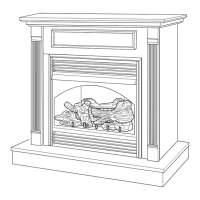
Figure 13 - Removing Firebox Bottom
Screws
Operating Blower
Light your gas appliance with the blower off.
After about 15 minutes, turn blower on to de-
liver heated air at the top louvers. The blower
features a variable control which allows you
to select the speed you desire.
Note: Periodically check louvers of the
rebox and remove any dust, dirt or other
obstructions.
INSTALLING LOG HEATER IN FIREBOX
CAUTION: Do not remove the
data plates attached to the heater
base assembly. The data plates
contain important warranty and
safety information.
CAUTION: Do not pick up log
base assembly by burners. This
could damage burners. Only
handle base by grates.
1. Remove four screws holding rebox bot-
tom in place.
2. Lift and remove firebox bottom (see
Figure 13).
3. If installing GA3750A blower acces-
sory (Model FB32CB only), see Installing
Blower Accessory, page 9.
4. Route exible gas line from manual shutoff
valve into rebox through side.
NOTICE: Most building codes
do not permit concealed gas
connections. A exible gas line
is recommended to allow ac-
cessibility from the rebox. The
exible gas supply line connec-
tion to the manual shutoff valve
should be accessible.
5. Install and properly test gas log heater.
Follow installation instructions included
with the vent-free gas log heater that is
being installed.
6. Replace rebox bottom and secure with
screws.
ASSEMBLING AND ATTACHING
OPTIONAL BRASS TRIM
Note: The instructions below show assem-
bling and attaching brass trim to replace.
1. Remove packaging from 3 pieces of
brass trim.
2. Locate 4 brass screws, 2 adjusting plates
with set screws and 2 shims in the hard-
ware packet.
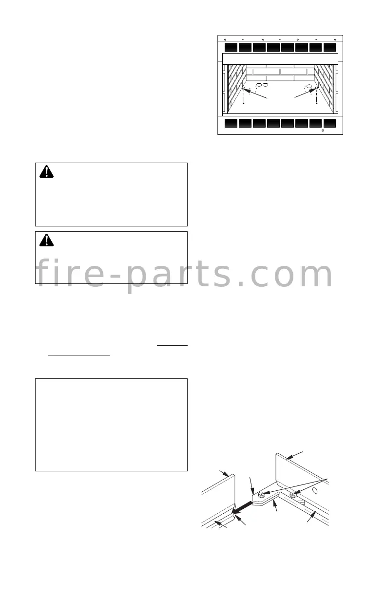
3. Align shim under adjusting plate as shown
in Figure 14.
4. Slide one end of adjusting plate/shim in
slot on mitered edge of top brass trim (see
Figure 14).
5. Slide other end of adjusting plate/shim
in slot on mitered edge of side brass trim
(see Figure 14).
6. While rmly holding edges of brass trim
together, tighten both set screws on the
adjusting plate with slotted screwdriver.
7. Repeat steps 1 through 6 for the other
side.
8. Tighten trim hanging screws (#10 x 6.25
shoulder) into holes in cabinets. Place
the assembled trim onto replace cabinet.
Align hanging notches on trim with hang-
ing screws on side of replace (see Figure
15, page 12). Push trim rmly into place,
sliding hanging notches over hanging
screws.
Figure 14 - Assembling Brass Trim
Slot
Mitered Edge
Shim
Set
Screws
Adjusting
Plate
Side
Brass
Trim
Top Brass
Trim
Slot
f i r e - p a r t s . c o m
 Loading...