Do you have a question about the Design Analysis H-350XL and is the answer not in the manual?
Details the different operating modes of the XL M data logger, such as SDI-12 Sensor Mode.
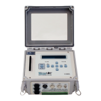
Illustrates and describes the physical input/output features on the front panel of XL M Series models.
Details how to test the installation after hooking up the battery and powering on the unit.
Explains how to navigate menus and use keys for configuring the XL M via its keypad and display.
Details the main menu structure, including status screens and sub menu headers for configuration.
Describes remote communication via command or menu interface using the first RS-232 serial port.
Explains general operations for navigating PC menu screens, activating options, and changing parameters.
Details the System Setup menu options, including time, date, site ID, and other system configurations.
Explains options for synchronizing the data logger's time clock with external sources like GPS or GOES radio.
Details the Serial Port Options menu, including baud rates, startup modes, and flow control settings.
Describes the hardware pin-out for the three RS-232 ports and their configurations.
Lists the functions and usage of each RS-232 port, including compatibility with various applications.
Details the "Configuration Files" submenu for saving, retrieving, and resetting setup information.
Lists the available status screens, showing system information like battery voltage and firmware version.
Describes how to view and interpret various status screens on the PC and built-in display.
Details the Scanning Options menu, including enabling/disabling scanning and setting data collection rates.
Explains specific scanning options like current time, next scan details, scan rate, and starting new files.
Details the menus for configuring stage and temperature readings, including units and averaging times.
Explains how to view and edit stage values, offsets, units, and averaging times for specific models.
Covers the setup for the internal temperature sensor, including unit selection and its use for pressure sensor compensation.
Explains how to set the remote stage value, source, offset, and slope for accurate measurements.
Details the Analog Input Options menus for configuring channels, offsets, slopes, samples, and ranges.
Explains how to configure slope, offset, samples, range, and differential mode for analog inputs.
Describes the physical connections for analog inputs and grounds on the terminal block.
Details the Digital I/O and Encoder Input/Output menus for configuring pin modes and functions.
Explains the different modes (input, output, encoder) and configurations for the digital I/O pins.
Covers using digital I/O pins to connect to or simulate quadrature shaft encoders.
Details the menus for configuring counter and frequency inputs, including counts, slopes, and intervals.
Explains options for setting counter values, total counts, slope, interval, mode, rate window, and debounce time.
Covers options for configuring frequency inputs, including slope and offset for converting frequency to meaningful units.
Details how to configure the logger to work with different SDI-12 sensors and measurement commands.
Explains how to configure the XL M as an SDI-12 sensor, defining its address and data values returned.
Explains how to set up logging features, including .NEW file settings, data formats, wrap mode, and column sources.
Guides the configuration of GOES radio setup options, including basic settings and transmission modes.
Details the configuration options for self-timed GOES transmissions, including channel, rate, and data format.
Explains how to configure random transmissions based on alarm conditions or other triggers.
Explains how to set up and use the ALERT system, covering radio enable, transmit offset, and source configurations.
Explains how to configure the data source, maximum, and minimum levels for the 4-20 mA output simulation.
Explains how to enable/disable alarms, set trigger modes, trigger points, reset points, and connection types.
Explains H-355 options like tank pressure, line pressure, bubble rate, purge pressure, duration, and auto purge settings.
States the XL M is maintenance-free but recommends calibration checks and adjustments for accuracy.
Provides troubleshooting tips for common problems like no SDI-12 response or intermittent data.
| Brand | Design Analysis |
|---|---|
| Model | H-350XL |
| Category | Data Loggers |
| Language | English |