INDEX
Page No. Topic
1. Index and Assembly Instructions
2. Safety Instructions
3. Maintenance and Storage
4. ETC ETC
ASSEMBLY INSTRUCTIONS
HANDLE ATTACHMENT (Pre delivery) (Refer to Figure 1)
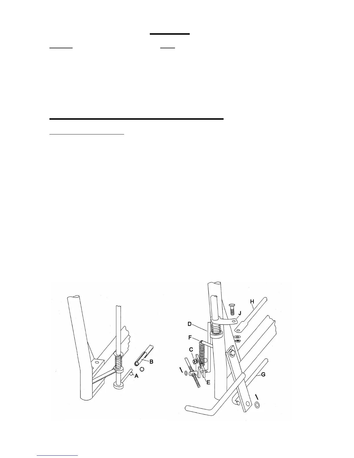
1. Connect the handles to the side rails of the chassis using four 75mm M8 bolts, while
making sure that the ball on gearbox linkage “ A” connects with the slotted tubular lever
“B.” The ball and the tube should be greased to make gear changes easier. The 75mm
bolt through the rear hole on the right of the mower (facing forward) will need to be
inserted from underneath. Fasten the four nuts securely.
2. Insert a ¾” circlip into the groove in the end of the tubular lever “B”.
3. Fully loosen nut “C” and connect rod “D” to the drive clutch lever “E” using the washer and
split pin. Retighten nut “C”.
4. Connect the clutch return spring to the top of the drive clutch lever and to pin “F”.
5. Connect the rod “G” to the foot pedal assembly using a washer and split pin.
6. Connect the height adjusting rod H to the curved lever “J” using the bolt nut and washer
provided.
7. See Figure 2. Place tank straps “L” in the tank bracket “K” slots and bend tabs up and
back against the bracket. Bolt the tank bracket to the handle bar assembly using three
round headed bolts, with the round heads of two bolts against the fuel tank. Place the fuel
tank in position and attach the straps at their lower end using two bolts.
8. Attach the throttle control to the handle bars ensuring the cable is free of sharp bends.
Ensure both “choke” and “stop” positions are achieved using the throttle lever.
9. Connect the fuel line from the tank to the engine.



 To Next Page