41
FIGURES, DIAGRAMS, AND VIEWS
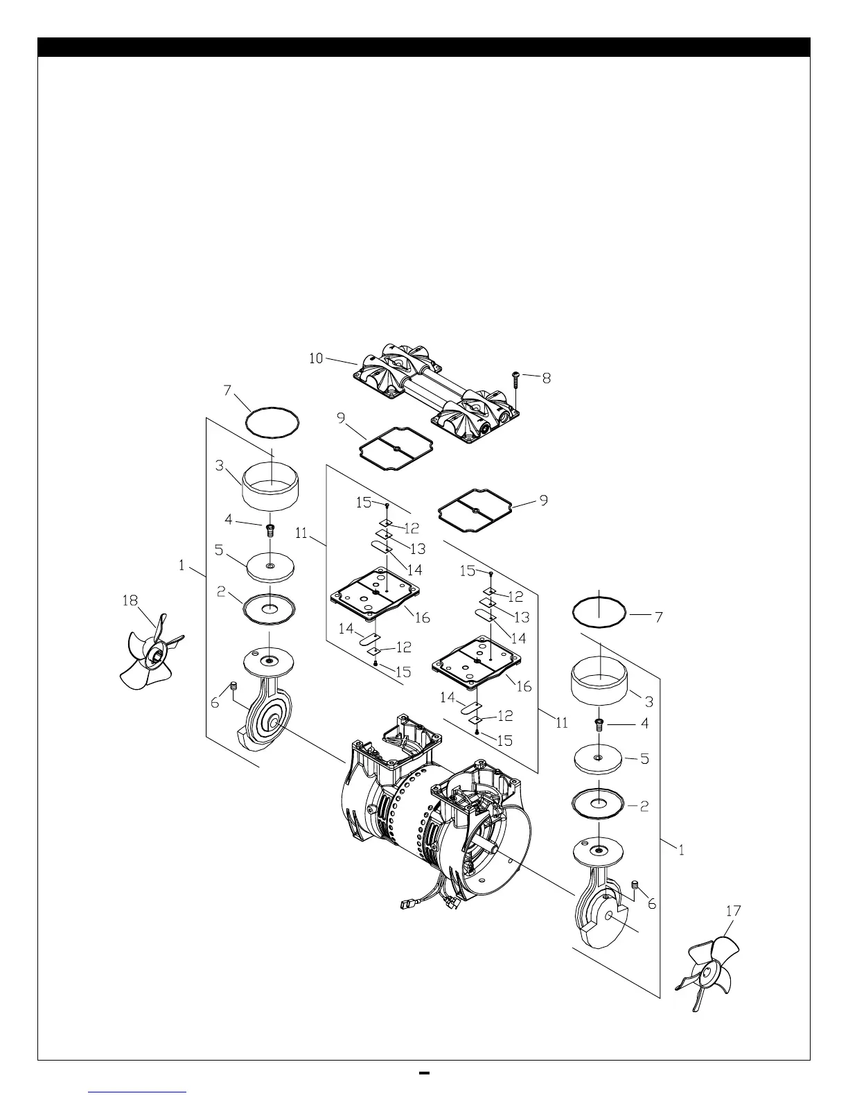
Figure 14 Compressor (exploded view)
1 Connecting rod, eccentric
and bearing assembly
2 Piston cup
3 Cylinder sleeve
4 Screw - piston cup retainer
5 Piston cup retainer
6 Set screw - eccentric
7 O-ring - sleeve
8 Screw - head
9 O-ring
10 Head
11 Valve plate assembly
12 Valve keeper strip
13 Valve restraint
14 Valve flapper - intake & exhaust
15 Screw - valve flapper
16 Valve plate
17 Fan - white
18 Fan - black
 Loading...