22
ENGLISH
Mains plug replacement
(U.K. & Ireland only)
● Should your mains plug need replacing and you
are competent to do this, proceed as instructed
below. If you are in doubt, contact an authorized
D
E WALT repair agent or a qualifi ed electrician.
● Disconnect the plug from the supply.
● Cut off the plug and dispose of it safely; a plug
with bared copper conductors is dangerous if
engaged in a live socket outlet.
● Only fi t 13 Amperes BS1363A approved plugs
fi tted with the correctly rated fuse (1).
● The cable wire colours, or a letter, will be
marked at the connection points of most
good quality plugs. Attach the wires to their
respective points in the plug (see below). Brown
is for Live (L) (2) and Blue is for Neutral (N) (4).
● Before replacing the top cover of the mains plug
ensure that the cable restraint (3) is holding the
outer sheath of the cable fi rmly and that the two
leads are correctly fi xed at the terminal screws.
Never use a light socket.
Never connect the live (L) or neutral (N)
wires to the earth pin marked E or
.
For 115 V units with a power rating exceeding 1500 W,
we recommend to fi t a plug to BS4343 standard.
Using an extension cable
If an extension cable is required, use an approved
extension cable suitable for the power input of
this machine (see technical data). The minimum
conductor size is 1.5 mm
2
. The cable has to have a
rubber jacket and a grounding conductor.
When using a cable reel, always unwind the cable
completely.
Also refer to the table below.
Conductor size (mm
2
) Cable rating (Amperes)
0.75 6
1.00 10
1.50 15
2.50 20
4.00 25
Cable length (m)
7.5 15 25 30 45 60
Voltage Amperes Cable rating (Amperes)
115 0 - 2.0 6 6 6 6 6 10
2.1 - 3.4 6 6 6 6 15 15
3.5 - 5.0 6 6 10 15 20 20
5.1 - 7.0 10 10 15 20 20 25
7.1 - 12.0 15 15 20 25 25 -
12.1 - 20.0 20 20 25 - - -
230 0 - 2.0 6 6 6 6 6 6
2.1 - 3.4 6 6 6 6 6 6
3.5 - 5.0 6 6 6 6 10 15
5.1 - 7.0 10 10 10 10 15 15
7.1 - 12.0 15 15 15 15 20 20
12.1 - 20.0 20 20 20 20 25 -
Assembly and adjustment
Prior to assembly and adjustment
always unplug the tool.
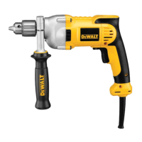
Inserting and removing a bit (fi g. A)
● Open the chuck by turning the sleeve (8)
counterclockwise and insert the bit shank.
● Place the bit in the chuck as far as it will go and
lift slightly before tightening.
● Tighten fi rmly by turning the sleeve clockwise.
● To remove the bit, proceed in reverse order.
Fitting the side handle (fi g. A)
The side handle (5) can be fi tted to suit both
RH- and LH-users.
Always use the drill with the side handle
properly assembled.
● Loosen the side handle.
● For RH-users, slide the side handle clamp over
the collar behind the chuck, handle at the left.
● For LH-users, slide the side handle clamp over
the colar behind the chuck, handle at the right.
 Loading...