English
8
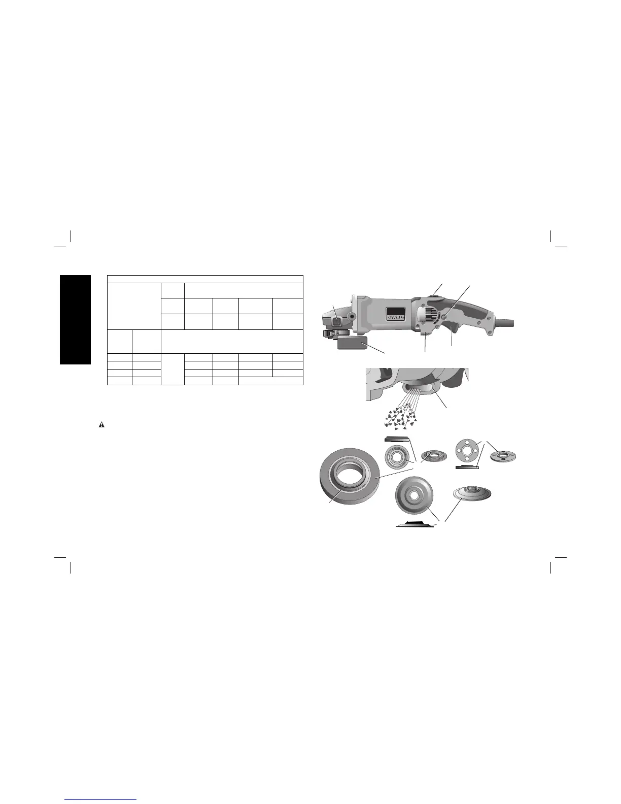
FIG. 1
G1
F
A
C
J
E
D
E
G2
H
B
Minimum Gauge for Cord Sets
Ampere Rating
Volts Total Length of Cord
in Feet (meters)
120 V 25
(7.6)
50
(15.2)
100
(30.5)
150
(45.7)
240 V 50
(15.2)
100
(30.5)
200
(61.0)
300
(91.4)
More
Than
Not
More
Than
AWG
0 6 18 16 16 14
610 1816 14 12
10 12 16 16 14 12
12 16 14 12 Not Recommended
SAVE THESE INSTRUCTIONS FOR
FUTUREUSE
COMPONENTS (Fig. 1)
WARNING: Never modify the power tool or any part of it. Damage
or personal injury could result.
A. Trigger Switch
B. Lock On Button
(D28065, D28115, D28116)
C. Spindle Lock Button
D. Type 27 Guard
E. Dust Ejection System™
(DES)
F. Yellow Rubber Ring
G1. 1-11/16" (43mm) diameter
quick-change backing flange
G2. 3" (76mm) diameter
stamped steel backing
flange (D28065, D28066N,
D28065N, D28116)
H. Threaded locking flange
I. Anti-Vibration Side Handle
(not shown)
J. Lock Off Button
(D28066N, only)