31
ENGLISH
WARNING: Use only
battery packs andchargers.
Inserting and Removing the Battery Pack
from the Tool (Fig. B)
NOTE: Make sure your battery pack
6
is fullycharged.
To Install the Battery Pack into the Tool Handle
1. Align the battery pack
6
with the rails inside the tool’s
handle (Fig. B).
2. Slide it into the handle until the battery pack is firmly seated
in the tool and ensure that you hear the lock snap intoplace.
To Remove the Battery Pack from the Tool
1. Press the release button
5
and firmly pull the battery pack
out of the toolhandle.
2. Insert battery pack into the charger as described in the
charger section of thismanual.
Fuel Gauge Battery Packs (Fig. B)
Some
battery packs include a fuel gauge which
consists of three green LED lights that indicate the level of
charge remaining in the batterypack.
To actuate the fuel gauge, press and hold the fuel gauge
button
20
. A combination of the three green LED lights will
illuminate designating the level of charge left. When the level
of charge in the battery is below the usable limit, the fuel gauge
will not illuminate and the battery will need to berecharged.
NOTE: The fuel gauge is only an indication of the charge left on
the battery pack. It does not indicate tool functionality and is
subject to variation based on product components, temperature
and end-userapplication.
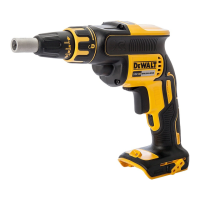
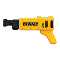
Changing Bit Holders (Fig. C)
1. Rotate the locking collar
3
1/4 turn to unlock nose cone
from gearcase.
2. Pull nose cone
4
off of gearcase.
3. To remove:
a. Grab the bit holder
22
.
b. Push it into the gear case depressing the sleeve
21
.
c. Rotate the bit holder until the clutchengages.
d. While holding the sleeve depressed, pull the bit
holderout.
4. Push and rotate the new bit holder into gearcase,
depressing the sleeve, until ball lock snaps in groove in bit
holdershank.
5. Replace nose cone
4
by placing on gear case and rotating
collar 1/4 turn to align arrow on gear case with the lock
symbol oncollar.
Changing Bit Tip (Fig. C)
1. Rotate the locking collar
3
1/4 turn to unlock nose cone
from gearcase.
2. Pull forward on nose cone
4
and remove it from
clutchhousing.
3. Use pliers to remove worn bit and install new bittip.
Depth Adjustment
Follow the graphic on the collar to increase or decrease the
fastening depth. To seat the screw deeper in the workpiece, turn
the adjustment collar to the right. To seat the screw higher in
the workpiece, turn the adjustment collar to theleft.
Prior to Operation
1. Make sure your battery pack is (fully)charged.
2. Insert the appropriate driveaccessory.
3. Select forward or reverserotation.
4. Set the appropriate drivingdepth.
OPERATION
Instructions for Use
WARNING: Always observe the safety instructions and
applicableregulations.
WARNING: To reduce the risk of serious personal
injury, turn tool off and disconnect battery pack
before making any adjustments or removing/
installing attachments or accessories. An accidental
start-up can causeinjury.
Proper Hand Position (Fig. D)
WARNING: To reduce the risk of serious personal injury,
ALWAYS use proper hand position asshown.
WARNING: To reduce the risk of serious personal
injury, ALWAYS hold securely in anticipation of a
suddenreaction.
Proper hand position requires one hand on the rear grip. Take
care to not block the air vents
24
.
Switching On and Off (Fig. A)
1. To run the tool, press the variable speed switch
7
. The
pressure exerted on the variable speed switch determines
the toolspeed.
2. To stop the tool, release the variable speed switch
7
.
Lock on Button
To lock the trigger switch
7
in the on position for continuous
operation, depress the trigger switch and push up the lock
on button
9
. The tool will continue to run. To turn the
tool off, from a locked on condition, squeeze and release
the trigger once. You will hear and see the lock on switch
returndownwards.
CAUTION: Before using the tool (each time) be sure
that the locking button release mechanism is working
freely. Be sure to release the locking mechanism before
disconnecting the battery. Failure to do so will cause
the tool to start immediately the next time the battery is
inserted. Damage or injury couldresult.
Screwdriving (Fig. A, D)
For best results, hold the screwdriver with your hand directly in
line with the fastener and press the variable speed switch with
the last one or two fingers of the hand. This reduces the chance
 Loading...