12
English
Forward/Reverse Control Button
(fig.1, 2)
WARNING: Always wait until the motor
has come to a complete standstill
before changing the direction ofrotation.
A forward/reverse control button(b) determines
the direction of the tool and also serves as a lock
offbutton.
To select forward rotation, release the trigger switch
and depress the for ward/re verse control button on
the right side of thetool.
To select reverse, release the trigger switch and
depress the forward/reverse control button on the
left side of thetool.
The center position of the control button locks the
tool in the off position. When changing the position
of the control button, be sure the trigger isreleased.
NOTE: The first time the tool is run after changing
the direction of rotation, you may hear a click on
start up. This is normal and does not indicate
aproblem.
Worklight (fig.1)
DCH273, DCH274
There is a worklight(d) located on the front of the
tool. The worklight will be activated when the trigger
switch is squeezed. The worklight is activated
when the trigger switch is depressed, and will
automatically turn off 20 seconds after the trigger
switch is released. If the trigger switch remains
depressed, the worklight will remainon.
NOTE: The worklight is for lighting the immediate
work surface and is not intended to be used as
aflashlight.
Selecting the Operating Mode (fig.1)
WARNING: Do not select the operating
mode when the tool isrunning.
Your tool is equipped with a separate mode
selector(c) to switch between rotary drilling, rotary
hammering and hammering onlymode.
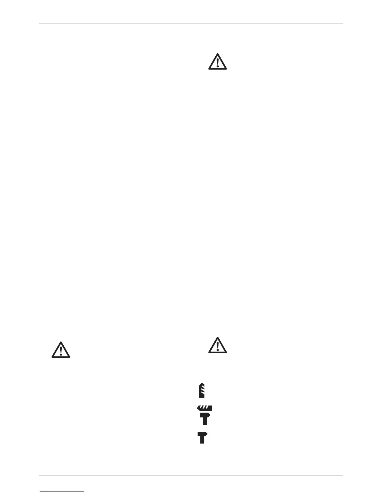
Rotary drilling: for screwdriving and for drilling
into steel, wood andplastics.
Rotary hammering: for concrete and
masonrydrilling.
Hammering only: for lightchipping.
Before attempting to rotate the mode selector
depress the mode selector button(u). For rotary
drilling, rotate the mode selector(c) until the arrow
TO REMOVE THE BATTERY PACK FROM THE TOOL
1. Press the battery release button(g) and firmly
pull the battery pack out of the toolhandle.
2. Insert battery pack into the charger as
described in the charger section of thismanual.
FUEL GAUGE BATTERY PACKS (FIG.3)
Some DeWALT battery packs include a fuel
gauge which consists of three green LED lights
that indicate the level of charge remaining in the
batterypack.
To actuate the fuel gauge, press and hold the fuel
gauge button(n). A combination of the three green
LED lights will illuminate designating the level of
charge left. When the level of charge in the battery
is below the usable limit, the fuel gauge will not
illuminate and the battery will need to berecharged.
NOTE: The fuel gauge is only an indication of the
charge left on the battery pack. It does not indicate
tool functionality and is subject to variation based
on product components, temperature and end-
userapplication.
Variable Speed Switch (fig.1)
To turn the tool on, squeeze the trigger switch(a). To
turn the tool off, release the trigger switch. Your tool
is equipped with a brake. The tool holder will stop as
soon as the trigger switch is fullyreleased.
The variable speed trigger switch enables you to
select the best speed for a particular application.
The farther you squeeze the trigger switch, the faster
the tool will operate. For maximum tool life, use
variable speed only for starting holes orfasteners.
NOTE: Continuous use in variable speed range is
not recommended. It may damage the switch and
should beavoided.
Side Handle (fig.1)
WARNING: To reduce the risk of
personal injury, ALWAYS operate
the tool with the side handle properly
installed. Failure to do so may result
in the side handle slipping during tool
operation and subsequent loss of
control. Hold tool with both hands to
maximizecontrol.
The side handle(e) clamps to the front of the gear
case and may be rotated 360˚ to permit right- or
left-hand use. The side handle must be tightened
sufficiently to resist the twisting action of the tool if
the accessory binds or stalls. Be sure to grip the
side handle at the far end to control the tool
during astall.
To loosen side handle, rotatecounterclockwise.
 Loading...