10
ENGLISH
Proper hand position requires one hand on the main handle
5
.
Switching On (Fig.A, D, E)
CAUTION: Do not point unit discharge at self
orbystanders.
CAUTION:
Always wear safety glasses. Wear
a filter mask if the operation is dusty. Use of gloves, long
pants and substantial footwear is recommended. Keep
long hair and loose clothing away from openings and
movingparts.
• To turn the blower on, slide the trigger switch
3
.
• To lock the blower on, turn the cruise control lever
4
,
clockwise as shown in FigureD. The blower runs at higher
speeds as the lever turns clockwise. The cruise control lever
Proper Hand Position (Fig. E)
WARNING: To reduce the risk of serious
personal injury, ALWAYS use proper hand position
asshown.
WARNING: To reduce the risk of serious
personal injury, ALWAYS hold securely in anticipation of a
suddenreaction.
WARNING:Do not operate blower without
tube securely in place. Never reach down into housing
through tubehole.
WARNING:Always slide the lock-off switch to
the locked position and remove the battery when:
- You leave blowerunattended.
- Checking, adjusting, cleaning, or working
onblower.
OPERATION
Instructions for Use
WARNING: Always observe the safety
instructions and applicableregulations.
WARNING: To reduce the risk of serious
personal injury, turn tool off and disconnect battery
pack before making any adjustments or removing/
installing attachments or accessories. An accidental
start-up can cause injury.
Inserting and Removing the Battery Pack
from the Tool (Fig. C)
NOTE: Make sure your battery pack
1
is fullycharged.
To Install the Battery Pack into the Tool Handle
1. Align the battery pack
1
with the rails inside the tool’s
handle (Fig. C).
2. Slide it into the handle until the battery pack is firmly seated
in the tool and ensure that you hear the lock snap intoplace.
To Remove the Battery Pack from the Tool
1. Press the release button
2
and firmly pull the battery pack
out of the toolhandle.
2. Insert battery pack into the charger as described in the
charger section of thismanual.
Fuel Gauge Battery Packs (Fig. C)
Some
battery packs include a fuel gauge which
consists of three green LED lights that indicate the level of
charge remaining in the batterypack.
To actuate the fuel gauge, press and hold the fuel gauge
button
13
. A combination of the three green LED lights will
illuminate designating the level of charge left. When the level
of charge in the battery is below the usable limit, the fuel gauge
will not illuminate and the battery will need to berecharged.
NOTE: The fuel gauge is only an indication of the charge left on
the battery pack. It does not indicate tool functionality and is
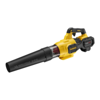
Tube Assembly (Fig. A–C)
CAUTION: Ensure the cruise control
lever
4
is in the locked position to prevent the trigger
switch
3
from moving and the battery pack
1
is removed
before attaching or removing the tube
6
. The tube must
be attached to the housing
7
beforeuse.
1. To attach the tube to the blower, line up the keyways
8
on
the side of the tube with the keys
9
on the side of the clear
duct opening as shown in FigureB. Push the tube into the
blower clear duct until the lock engages thetube.
2. Pull on the tube to ensure it is securely inplace.
3. To remove the tube, insert a screwdriver into the unlocking
holes
10
on the sides of the tube to depress the tabs of the
clearduct.
4. Pull the tube off the clearhousing.
ASSEMBLY AND ADJUSTMENTS
WARNING: To reduce the risk of serious
personal injury, turn tool off and disconnect battery
pack before making any adjustments or removing/
installing attachments or accessories. An accidental
start-up can causeinjury.
WARNING: Use only
battery packs
andchargers.
subject to variation based on product components, temperature
and end-userapplication.

 Loading...