13
ENGLISH
Saw Chain and Guide Bar Oiling (Fig. A)
Auto Oiling System
This chainsaw is equipped with an auto oiling system that keeps
the saw chain and guide bar constantly lubricated. The oil level
indicator
9
shows the level of the oil in the chainsaw. If the
oil level is less than a quarter full, remove the battery from the
chainsaw and refill with the correct type of oil. Always empty oil
tank when finishedcutting.
Replacement chain and bar are available from your
nearest authorized servicecenter.
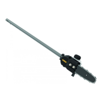
• The DCMCS574 chain saw requires a replacement 45cm chain
DT20688-QZ
and a replacement 45cm
bar
DT20687-QZ
.
• The DCMCS575 chain saw requires a replacement 50cm chain
DT20690-QZ
and a replacement 50cm
bar
DT20689-QZ
.
Replacing the Saw Chain (Fig. A, E, H)
CAUTION: Sharp chain. Always wear protective gloves
when handling the chain. The chain is sharp and can cut
you when it is notrunning.
WARNING: Sharp moving chain. To prevent accidental
operation, ensure the battery is removed from the tool is
unplugged before performing the following operations.
Failure to do this could result in serious personalinjury.
1. To remove the saw chain
5
, place the saw on a flat,
firmsurface.
2. Remove sprocket cover
6
as described in Installing the
Guide Bar and Saw Chainsection.
3. Rotate the chain tension screw
8
using the flat screwdriver
end of thewrench
17
. Turning the screw counterclockwise
allows the guide bar
4
to recede and reduces the tension on
the chain so that it may beremoved.
4. Wearing protective gloves, grasp the saw chain and lift the
worn saw chain out of the groove in the guidebar.
5. Flip guide bar over every time you replace the chain to
ensure evenwear.
6. Place the new chain in the slot of the guide bar, making sure
the saw teeth are facing the correct direction by matching
the arrow and graphic of the saw chain on the sprocket
cover
6
shown in Fig.H.
7. Follow instructions for Installing the Guide Bar and
SawChain.
2. To adjust saw chain tension, loosen bar lock nuts
7
.
3. Rotate the chain tension screw
8
located on the sprocket
cover using the flat screwdriver end of thewrench
17
.
4. Check saw chain tension, adjust ifneeded.
5. Do not over-tension the saw chain as this will lead to
excessive wear and will reduce the life of the guide bar and
sawchain.
6. Once saw chain tension is correct, tighten bar lock
nuts
7
untiltight using 6ft. lbs. (8 Nm) oftorque
.
7. A new chain stretches slightly during the first few hours of
use. It is important to check the tension frequently (after
removing the battery pack) during the first 2hours ofuse.
Adjusting Chain Tension (Fig. A, E–G)
NOTE: Saw chain tension should be adjusted regularly before
eachuse.
1. With the saw still on a firm surface check the saw chain
5
tension. The tension is correct when the saw chain snaps
back after being pulled 6mm away from the guide bar
4
with light force from the middle finger and thumb as shown
in Fig.F. There should be no “sag” between the guide bar
and the saw chain on the underside as shown in Fig.G.
Installing the Guide Bar and Saw Chain
(Fig. A, E–G)
CAUTION: Sharp chain. Always wear protective gloves
when handling the chain. The chain is sharp and can cut
you when it is notrunning.
WARNING: Sharp moving chain. To prevent accidental
operation, ensure the battery is removed from the tool
before performing the following operations. Failure to do
this could result in serious personalinjury.
If the saw chain
5
and guide bar
4
are packed separately in the
carton, the chain has to be attached to the bar, and both must
be attached to the body of thetool.
1. Place the saw on a flat, firmsurface.
2. Rotate the bar lock nuts
7
counterclockwise with the
wrench
17
provided.
3. Remove sprocket cover
6
, and bar lock nuts
7
.
4. Wearing protective gloves, grasp the saw chain
5
and wrap
it around the guide bar
4
, ensuring the teeth are facing the
correctdirection.
5. Ensure the chain is properly set in the slot around the entire
guidebar.
6. Place the saw chain around the sprocket
20
. While lining
up the slot on the guide bar with chain tensioning pin
21
,
and the bolts
22
, on the base of the tool as shown in Fig.E.
7. Once in place, hold the bar still, replace sprocket cover
6
.
Make sure bolt holes on the cover line up with the bolts
22
,
on the mainhousing.
8. Install the bar lock nuts
7
and rotate clockwise with the
wrench
17
provided
until snug
, then loosen the nut(s) one
full turn, so that the saw chain can be properlytensioned.
9. Using the flat screwdriver end of thewrench
17
rotate the
chain tensioning screw
8
clockwise to increase tension.
Make sure the saw chain
5
is snug around the guide bar
4
as shown in Fig.F and Fig.G then tighten the bar lock
nut(s)
7
untilsnug.
10. Follow the instructions in the section Adjusting
ChainTension.
illuminate designating the level of charge left. When the level
of charge in the battery is below the usable limit, the fuel gauge
will not illuminate and the battery will need to berecharged.
NOTE: The fuel gauge is only an indication of the charge left on
the battery pack. It does not indicate tool functionality and is
subject to variation based on product components, temperature
and end-userapplication.
 Loading...