9
ENGLISH
mental abilities; lack of experience, knowledge or skills
unless they are supervised by aperson responsible for their
safety. Children should never be left alone with this product.
ASSEMBLY AND ADJUSTMENTS
English (original instructions)
WARNING: Pinch and impact hazard. Do not cut the
large securing cable ties (
34
Fig. B) until instructed
to do so later in the manual. The spring loaded
mechanism is under tension and can open unexpectedly,
with high force. To reduce the risk of serious personal
injury, do not raise or lower stand until the assembly is
complete.
Tools Required for Assembly (Fig. A)
• Hex wrench
5
(supplied, comes in the wrench storage
location in the corner of the stand)
• Adjustable wrench
• 13 mm open end wrench
• 18 mm open end wrench
• Wire cutting pliers
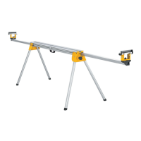
NOTE: This rolling mitre saw stand is astand designed to
accommodate most mitre saws and to provide portability for
those units, both in the field and in the shop.
Wrench Storage (Fig. A)
The supplied hex wrench
5
comes in the wrench storage
location in the corner of the stand.
Attaching the Leg Extension (Fig. B, C)
IMPORTANT: Place stand upside down on the floor or on
alevel, stable table as shown in Figure B.
1. With stand upside down, insert the leg extension
4
in the
stand.
2. Align the holes and install two M8 × 16 mm button head
screws
17
with curved washers
18
.
3. Tighten securely with the supplied hex wrench
5
.
Attaching the Storage Foot to Stand (Fig. D)
1. With the stand upside down, lift the end opposite the leg
extension and insert the storage foot
2
into the stand with
the u-shape tube upside down.
2. Align the holes and install one M8 × 16 mm button head
screw
17
with one curved washer
18
on each side.
3. Tighten securely with the supplied hex wrench
5
.
Attaching the Handle (Fig. E)
1. With stand upside down, attach the handle
8
on the end
of the stand opposite the wheels with one M8 × 21 mm
button head screw
21
and lock washer
22
. Install screw
using supplied hex wrench, but do not tighten securely.
2. Turn the stand right side up so the wheels and leg extension
sit level on the floor or stable table. Ensure the stand
remains in the closed position, do not raise the stand.
3. Install one M6 × 10 mm button head screw
19
and lock
washer
20
on the other side. Tighten securely with the
supplied hex wrench.
4. Tighten M8 × 21 mm button head screw
21
added in STEP
1 securely with the supplied hex wrench.
Attaching the Wheels (Fig. F, G)
1. Slide awasher
15
and bushing
14
on to the axle bolt
13
.
2. Continuing with stand upside down, insert the axle bolt into
the wheel
3
and the wheel extension
23
on the frame as
shown in Figure F. NOTE: Ensure the ribbed side of wheel
hub is facing inward toward the frame assembly.
3. Place awasher
15
and locking nut
16
on the threaded end
of the axel bolt.
4. Tighten the axle bolt and nut using a13 mm wrench and an
adjustable wrench.
NOTE: Do not overtighten. Overtightening may cause
wheel rotation to be impaired.
5. Attach the other wheel in the same manner.
To Raise and Lower the Stand (Fig. A, H,
N–O)
WARNING: PINCH AND IMPACT HAZARD. The spring
loaded mechanism is under tension and can open
unexpectedly, with high force.
1. Turn the stand right side up on the floor.
IMPORTANT: Stand must be right side up when cutting
white cable ties
34
.
2. While holding down on the top of the stand frame, use wire
cutting pliers to cut the white cable ties.
IMPORTANT: DO NOT cut the black cable ties securing
the cables that open the stand.
3. Place one foot on the bottom of the leg extension
4
. Hold
the handle down with one hand, push the red activating
lever
12
to disengage the latching mechanism.
4. Lift the handle
8
with both hands while simultaneously
pushing the red lever.
The Stand Has Three Positions: Closed, Fully
Extended and Intermediate
To Reach the Intermediate Position
Lift up on the handle and slowly raise the stand. The stand will
stop at the intermediate position. Release the lever.
NOTE: When in the intermediate position, the stand will lower
slightly when atool is placed on it. The intermediate position
does not lock against upward motion. The stand relies on the
weight of the tool to remain in the intermediate position.
To Fully Extend Stand
Start in the intermediate position. Repeat STEPS 3–4. Lift up on
the handle and raise the stand to the fully extended position.
The stand will latch in the fully extended position. Release the
lever.
To Close Stand
Repeat STEPS 3–4. You must lift up on the handle and then
push down until the stand is closed. Release the lever.
IMPORTANT: Lift the handle first to disengage latch before able
to lower stand.
 Loading...