ENGLISH
10
WARNING: Before connecting the tool to a power
supply, be sure the slider switch is in the off position
by pressing the rear part of the switch and releasing.
Ensure the slider switch is in the off position as
described above after any interruption in power
supply to the tool, such as the activation of a ground
fault interrupter, throwing of a circuit breaker,
accidental unplugging, or power failure. If the slider
switch is locked on when the power is connected, the
tool will startunexpectedly.
To start the tool, slide the ON/OFF slider switch
8
toward
the front of the tool. To stop the tool, release the ON/OFF
sliderswitch.
For continuous operation, slide the switch toward the front
of the tool and press the forward part of the switch inward.
To stop the tool while operating in continuous mode, press
the rear part of the slider switch andrelease.
Spindle Lock (Fig. A)
The spindle lock
2
is provided to prevent the spindle from
rotating when installing or removing wheels. Operate the
spindle lock only when the tool is turned off, unplugged
from the power supply, and has come to a completestop.
NOTICE: To reduce the risk of damage to the tool, do
not engage the spindle lock while the tool is operating.
Damage to the tool will result and attached accessory
may spin off possibly resulting ininjury.
To engage the lock, depress the spindle lock button
and rotate the spindle until you are unable to rotate the
spindlefurther.
Surface Finishing of Masonry and Stone
NOTE: The amount of dust retained by the dust extractor
vacuum is dependent on its filter system. Refer to the dust
extractor vacuum instruction manual for moreinformation.
1. Ensure all assembly instructions have beencompleted.
2. Turn the dust extractor vacuum on as instructed in the
dust extractor vacuum instructionmanual.
3. Turn the tool on as instructed in the tool instruction
manual and allow it to reach full speed before making
contact with worksurface.
4. Place the surface finishing shroud to flat work surface
such as a floor or wall and begingrinding.
5. When surface finishing is complete, turn the tool off and
disconnect from the power source. Allow the tool to
stop rotating before laying itdown.
NOTE: The surface finishing shroud and dust extractor
vacuum will only be effective when used with a diamond
surface cup wheel on a flatsurface.
Handles
Attaching Side Handle (Fig. A)
WARNING: Before using the tool, check that the
handle is tightenedsecurely.
Screw the side handle
17
tightly into one of the holes on
either side of the gear case. The side handle should always
be used to maintain control of the tool at alltimes.
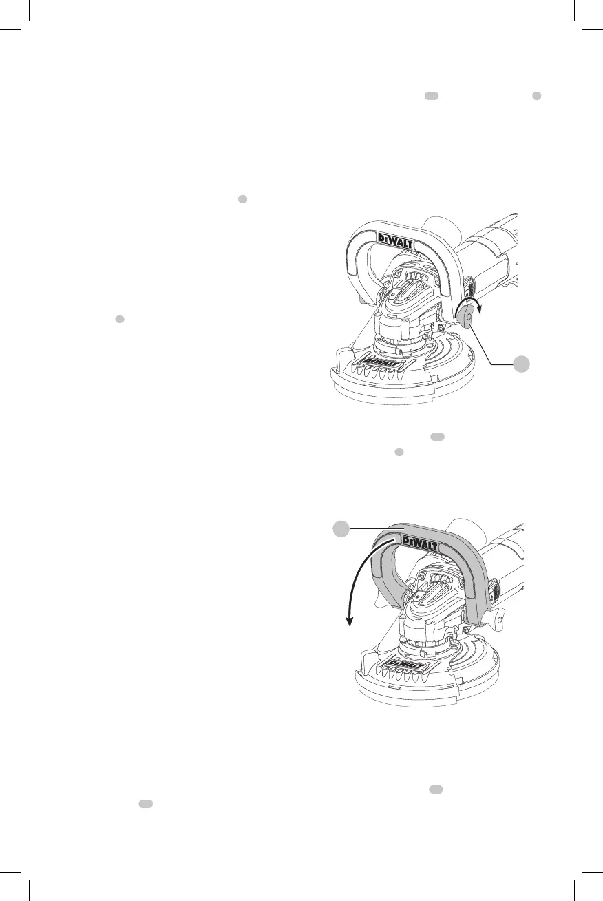
Installation of the bail handle assembly
(Fig I, J)
1. Lightly pull thumbscrews
27
outwards from handle
5
so that their threaded ends are pulled insidehandle.
2. Place the handle assembly over the grinder gear case
aligning the thumbscrews with the threaded holes
and the ears on the gear case with the slots in the bail
handleassembly.
3. Tighten the thumbscrews to secure the handle to
thegrinder.
Fig. I
27
Adjustment of the bail handle angle
1. Loosen both thumbscrews
27
2 fullturns.
2. Rotate the handle
5
to the desired 45˚ or 90˚ position
making sure that the detent grovesalign.
3. Re-tighten the thumbscrews to secure the handle to
thegrinder.
Fig. J
5
Edging Use Application (Fig. A)
This concrete grinding shroud has a door feature to allow
flush grinding against awall.
1. Turn off the tool and disconnect from the powersource.
2. Using the edging door tab
16
, rotate the edging door
until it snaps into the openpostion.
3. Connect the tool to the powersource.