11
ENGLISH
Removing the Blade
1. Unplug thesaw.
2. Insert the 6mm hex key
28
into the opposite location of the blade
shaft and hold it(Fig.E).
3. Use second hex key
28
as shown in Figure E as spindlelock.
4. Loosen the blade bolt
5
by turning clockwise. Remove the blade bolt
and the outer flange
4
.
5. Press the lower guard lock-up release lever
2
to raise the lower blade
guard
6
and remove the saw blade
7
.
Installing a Blade
1. Unplug thesaw.
2. Install the new saw blade onto the shoulder provided on the inner
flange
35
making sure that the teeth at the bottom edge of the blade
are pointing towards the fence (away from the operator).
3. Replace the outer flange
4
, making sure that the location lugs
36
are
engaged correctly, one on each side of the motorshaft.
4. Tighten the blade bolt
5
by turning counterclockwise while holding
the 6mm hex key
28
engaged with your other hand (Fig.E).
WARNING: Be aware the saw blade shall be replaced in the described
way only. Only use saw blades as specified under Technical Data;
Cat. no.: DT4282 issuggested.
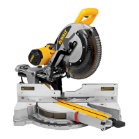
Transporting the Saw (Fig.A, B)
WARNING: To reduce the risk of serious personal injury,
ALWAYS lock the rail lock knob, mitre latch, bevel clamp handle, lock
down button and fence lock knobs before transporting saw. Never use
guards for transporting or liftup.
• Before transporting the saw, verify that the cord isdisconnected.
• To transport the saw, lower the head and depress the lock down
button
25
.
• Lock the rail lock knob with the saw head in the front position, lock the
mitre arm in the full left mitre angle, slide the fence
15
completely
inward and lock the fence lock knobs, then lock the bevel clamp
handle
21
with the saw head in the vertical position to make the tool
as compact aspossible.
• Always use the base extension handles
20
to carry thesaw.
ADJUSTMENTS
WARNING: To reduce the risk of injury, turn unit off and
disconnect machine from power source before installing and
removing accessories, before adjusting or changing set-ups
or when making repairs. Be sure the trigger switch is in the OFF
position. An accidental start-up can causeinjury.
Your mitre saw was accurately adjusted at the factory. If readjustment
due to shipping and handling or any other reason is required, follow the
steps below to adjust your saw. Once made, these adjustments should
remainaccurate.
Adjusting the Rails for Constant Cutting Depth
(Fig.A,B,F, G)
The blade must run at a constant cutting depth along the full length of the
table and must not touch the fixed table at the rear of the slot or at the front
of the rotating arm. To achieve this, the rails
26
must be perfectly parallel to
the table when the saw head is fullydepressed.
1. Press the lower guard lock up release lever
2
(Fig.A).
2. Press the saw head fully to the rear position and measure the height
from the rotating table
12
to the bottom of the outer flange
4
(Fig.G).
3. Loosen the rail lock knob
17
(Fig.B).
4. Keeping the saw head fully depressed, pull the head to the end of
itstravel.
5. Measure the height indicated in FigureG again. Both values should
beidentical.
6. If adjustment is required, proceed as follows (Fig. F):
a. Loosen the locknut
37
in the bracket
38
under the upper dust
extraction nozzle and adjust the screw
39
as required, proceeding in
smallsteps.
b. Tighten the locknut
37
.
WARNING: Always check that the blade does not touch the table at
the rear of the slot or at the front of the rotating arm at 90° vertical
and 45° bevel positions. Do not switch on before having checked this!
Adjusting the Fence (Fig.H)
Lift the sliding fence lock lever
40
counterclockwise to loosen. Move the
sliding fence
15
to a position that avoids the blade, then tighten the fence
lock lever by turningclockwise.
WARNING: The guide grooves can become clogged with sawdust. Use
a stick or some low pressure air to clear the guidegrooves.
Checking and Adjusting the Blade to the Fence
(Fig.A, B,I, J)
1. Slacken the mitre latch
11
.
2. Place your thumb on the mitre arm
10
and squeeze the mitre latch
11
to release the rotating table/mitre arm
12
.
3. Swing the mitre arm until the latch locates it at the 0° mitreposition.
4. Pull down the head and lock it in this position using the lock-down
button
25
.
5. Check that the two 0° markings
41
on the mitre scale
13
are
justvisible.
6. Place a square
42
against the left side of the fence
15
and blade
7
.
WARNING: Do not touch the tips of the blade teeth with thesquare.
7. If adjustment is required, proceed as follows:
a. Loosen the mitre scale screws
14
(Fig.I) and move the scale/mitre
arm assembly left or right until the blade is at 90° to the fence as
measured with the square
42
(Fig.J).
b. Retighten the mitre scale screws
14
.
Checking and Adjusting the Blade to the Table
(Fig.B,K–M)
1. Loosen the bevel clamp handle
21
(Fig.K).
2. Press the saw head to the right to ensure it is fully vertical and tighten
the bevel clamphandle.
3. Place a square
42
on the table and up against the saw blade
7
(Fig.L).
WARNING: Do not touch the tips of the blade teeth with thesquare.
4. If adjustment is required, proceed as follows:
a. Loosen the bevel clamp handle
21
and turn the vertical position
adjustment stop screw
43
in or out with the hex wrench (as shown
in Fig. K) until the blade is at 90° to the table as measured with
thesquare.
b. If the bevel pointer
46
does not indicate zero on the bevel scale
24
,
loosen the bevel scale screws
45
that secure the scale and move the
scale asnecessary.
Checking and Adjusting the Bevel Angle (Fig.K, M)
The bevel override allows the maximum bevel angle to be set at 45° or 48°
asrequired.
- Left = 45°
- Right = 48°
1. Make sure the override lever
44
is located in the leftposition.
2. Loosen the bevel clamp handle
21
by pulling it outward then down
and move the saw head to theleft.
3. This is the 45° bevelposition.

 Loading...