9
ENGLISH
Visible radiation. Do not stare into light.
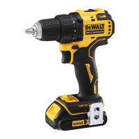
Date Code Position (Fig. C)
The date code
10
, which also includes the year of manufacture,
is printed into thehousing.
Example:
2019 XX XX
Year of Manufacture
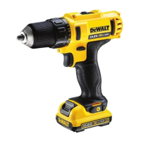
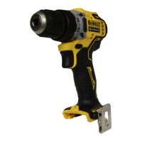
Description (Fig. A)
WARNING: Never modify the power tool or any part of it.
Damage or personal injury couldresult.
1
Variable speed trigger
switch
2
Forward/reverse control
button
3
Torque adjustment collar
4
Gear shifter
5
Keyless chuck
6
Battery release button
7
Battery pack
8
Worklight
Intended Use
This drill/driver is designed for light fastening and
drillingapplications.
DO NOT use under wet conditions or in the presence of
flammable liquids orgases.
This drill/driver is a professional powertool.
DO NOT let children come into contact with the tool.
Supervision is required when inexperienced operators use
thistool.
• Young children and the infirm. This appliance is not
intended for use by young children or infirm persons
withoutsupervision.
• This product is not intended for use by persons (including
children) suffering from diminished physical, sensory or
mental abilities; lack of experience, knowledge or skills
unless they are supervised by a person responsible for their
safety. Children should never be left alone with thisproduct.
ASSEMBLY AND ADJUSTMENTS
WARNING: To reduce the risk of serious personal
injury, turn tool off and disconnect battery pack
before making any adjustments or removing/
installing attachments or accessories. An accidental
start-up can causeinjury.
WARNING: Use only
battery packs andchargers.
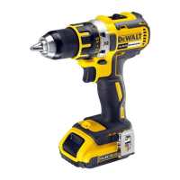
Inserting and Removing the Battery Pack
from the Tool (Fig. C)
NOTE: Make sure your battery pack
7
is fullycharged.
To Install the Battery Pack into the Tool Handle
1. Align the battery pack
7
with the rails inside the tool’s
handle (Fig. C).
2. Slide it into the handle until the battery pack is firmly seated
in the tool and ensure that you hear the lock snap intoplace.
To Remove the Battery Pack from the Tool
1. Press the release button
6
and firmly pull the battery pack
out of the toolhandle.
2. Insert battery pack into the charger as described in the
charger section of thismanual.
OPERATION
Instructions for Use
WARNING: Always observe the safety instructions and
applicableregulations.
WARNING: To reduce the risk of serious personal
injury, turn tool off and disconnect battery pack
before making any adjustments or removing/
installing attachments or accessories. An accidental
start-up can causeinjury.
Proper Hand Position (Fig. A, H)
WARNING: To reduce the risk of serious personal injury,
ALWAYS use proper hand position asshown.
WARNING: To reduce the risk of serious personal
injury, ALWAYS hold securely in anticipation of a
suddenreaction.
Proper hand position requires one hand on the main handle
9
.
Variable Speed Trigger Switch (Fig. A)
To turn the tool on, squeeze the trigger switch
1
. To turn
the tool off, release the trigger switch. Your tool is equipped
with a brake. The chuck will stop when the trigger switch is
fullyreleased.
The variable speed switch enables you to select the best speed
for a particular application. The further you squeeze the trigger,
the faster the tool will operate. For maximum tool life, use
variable speed only for starting holes or fasteners.
NOTE: Continuous use in variable speed range is not
recommended. It may damage the switch and should
beavoided.
Forward/Reverse Control Button (Fig. A)
A forward/reverse control button
2
determines the direction of
the tool and also serves as a lock-offbutton.
To select forward rotation, release the trigger switch and
depress the forward/reverse control button on the right side of
thetool.
To select reverse, depress the forward/reverse control button on
the left side of the tool. The center position of the control button
locks the tool in the off position. When changing the position of
the control button, be sure the trigger isreleased.
NOTE: The first time the tool is run after changing the direction
of rotation, you may hear a click on start up. This is normal and
does not indicate aproblem.
Worklight (Fig. A)
There is a worklight
8
located under the torque adjustment
collar
3
. The worklight will be activated when the trigger switch
issqueezed.