9
ENGLISH
Markings on Tool
The following pictograms are shown on the tool:
a
Read instruction manual beforeuse.
n
Visible radiation. Do not stare intolight.
Date Code Position (Fig.B)
The date code
8
, which also includes the year of manufacture,
is printed into thehousing.
Example:
2021XX XX
Year and Week of Manufacture
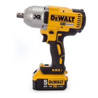
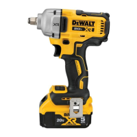
Description (Fig. A, B)
WARNING: Never modify the power tool or any part of it.
Damage or personal injury couldresult.
1
Trigger switch
2
Forward/reverse button
3
Anvil
4
Battery release button
5
Battery pack
6
Worklight
7
Mode selector
8
Belt hook
9
Screw
10
Main handle
Intended Use
These impact wrenches are designed for professional impact
fastening applications. The impact function makes this
tool particularly useful for driving fasteners in wood, metal
andconcrete.
DO NOT use under wet conditions or in the presence of
flammable liquids orgases.
These impact wrenches are professional powertools.
DO NOT let children come into contact with the tool.
Supervision is required when inexperienced operators use
thistool.
• Young children and the infirm. This appliance is not
intended for use by young children or infirm persons
withoutsupervision.
• This product is not intended for use by persons (including
children) suffering from diminished physical, sensory or
mental abilities; lack of experience, knowledge or skills
unless they are supervised by a person responsible for their
safety. Children should never be left alone with thisproduct.
ASSEMBLY AND ADJUSTMENTS
WARNING: To reduce the risk of serious personal
injury, turn tool off and disconnect battery pack
before making any adjustments or removing/
installing attachments or accessories. An accidental
start‑up can causeinjury.
WARNING: Use only DeWALT battery packs andchargers.
Inserting and Removing the Battery Pack
from the Tool (Fig.J)
NOTE: Make sure your battery pack
5
is fullycharged.
To Install the Battery Pack into the Tool Handle
1. Align the battery pack
5
with the rails inside the tool’s
handle (Fig. J).
2. Slide it into the handle until the battery pack is firmly seated
in the tool and ensure that you hear the lock snap intoplace.
To Remove the Battery Pack from the Tool
1. Press the release button
4
and firmly pull the battery pack
out of the toolhandle.
2. Insert battery pack into the charger as described in the
charger section of thismanual.
Fuel Gauge Battery Packs (Fig.B)
Some DeWALT battery packs include a fuel gauge which
consists of three green LED lights that indicate the level of
charge remaining in the batterypack.
To actuate the fuel gauge, press and hold the fuel gauge
button
12
. A combination of the three green LED lights will
illuminate designating the level of charge left. When the level
of charge in the battery is below the usable limit, the fuel gauge
will not illuminate and the battery will need to berecharged.
NOTE: The fuel gauge is only an indication of the charge left on
the battery pack. It does not indicate tool functionality and is
subject to variation based on product components, temperature
and end‑userapplication.
Belt Hook (OptionalAccessory) (Fig.A)
WARNING: To reduce the risk of serious personal
injury, DO NOT suspend tool overhead or suspend
objects from the belt hook. ONLY hang tool’s belt hook
from a workbelt.
WARNING: To reduce the risk of serious personal
injury, ensure the screw holding the belt hook issecure.
CAUTION: To reduce the risk of personal injury or
damage, DO NOT use the belt hook to hang the drill
while using as aspotlight.
IMPORTANT: When attaching or replacing the belt hook, use
only the screw
9
that is provided. Be sure to securely tighten
thescrew.
The belt hook
8
can be be attached to either side of the tool
using only the screw
9
provided, to accommodate left‑ or
right‑ handed users. If the hook is not desired at all, it can be
removed from thetool.
To move belt hook, remove the screw
9
that holds it in place
then reassemble on the opposite side. Be sure to securely
tighten thescrew.
Variable Speed Trigger Switch (Fig.A)
To turn the tool on, squeeze the trigger switch
1
. To turn the
tool off, release the trigger switch. Your tool is equipped with
a brake. The anvil will stop when the trigger switch is fully
 Loading...