8) Use diagram to locate holes in driver’s side toolbox.
9) Drill 2.5” hole with hole saw and use molding to protect
hoses from rough edges.
10) Drill 3/8” holes for pump as indicated and bolt pump to
inside of toolbox.
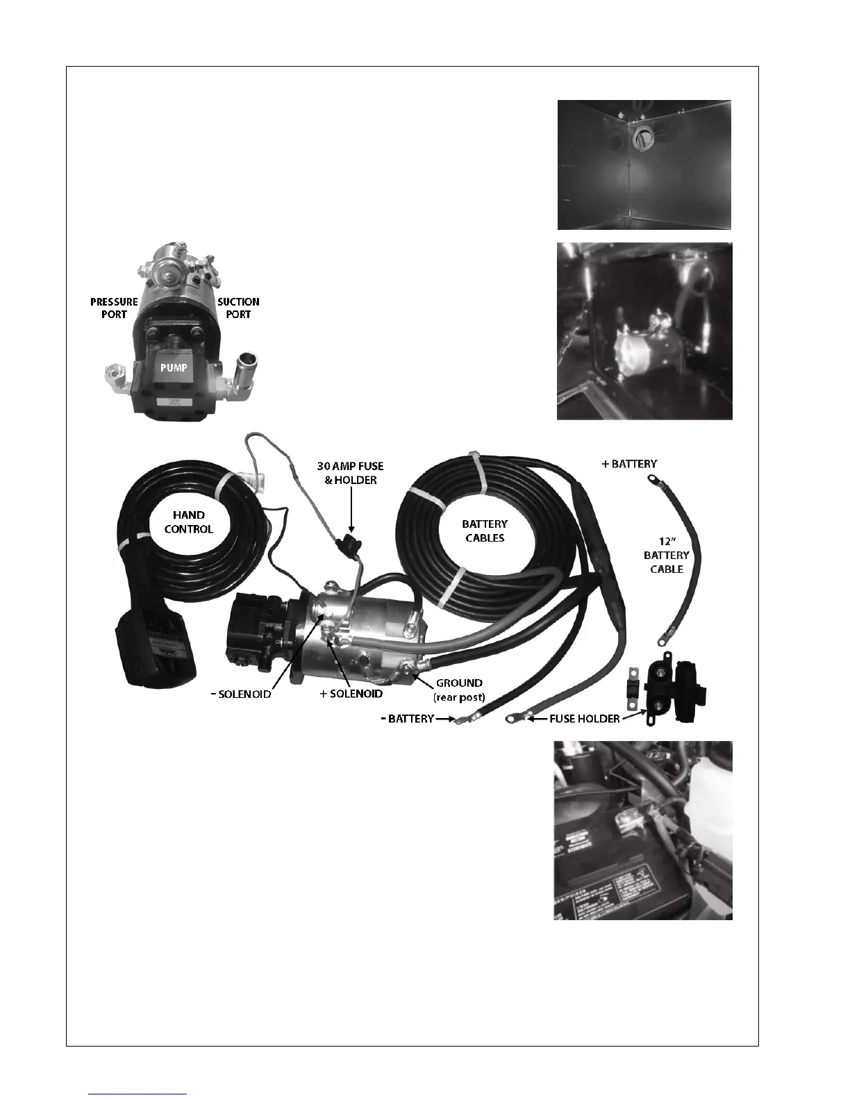
11) Attach suction hose and
pressure hose to pump with
adapters provided.
12) Attach suction hose to bottom of
reservoir as indicated in diagram.
13) Attach black wire from hand
control to negative terminal on
solenoid.
14) Attach 30-amp fuse holder to positive terminal on
solenoid and then to red wire from hand control.
15) Run battery cables through hole in toolbox and attach to
E/H motor as indicated (black cable to rear post).
16) Run battery cables along frame rail and attach black
cable to negative terminal on battery.
17) Attach 200-amp fuse holder to 12” battery cable on one
end and red battery cable on other end.
18) Insert 200-amp fuse and attach 12” battery cable to positive terminal on battery.
19) Test unit to ensure that all functions operate correctly and check for oil leaks.
 Loading...